From Instructions to Inventor File
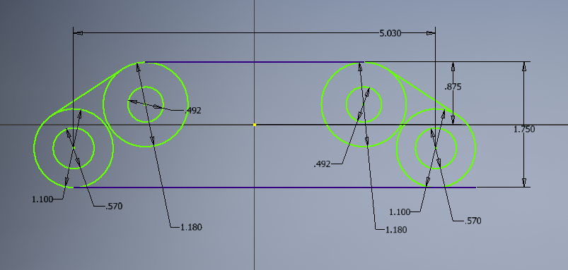
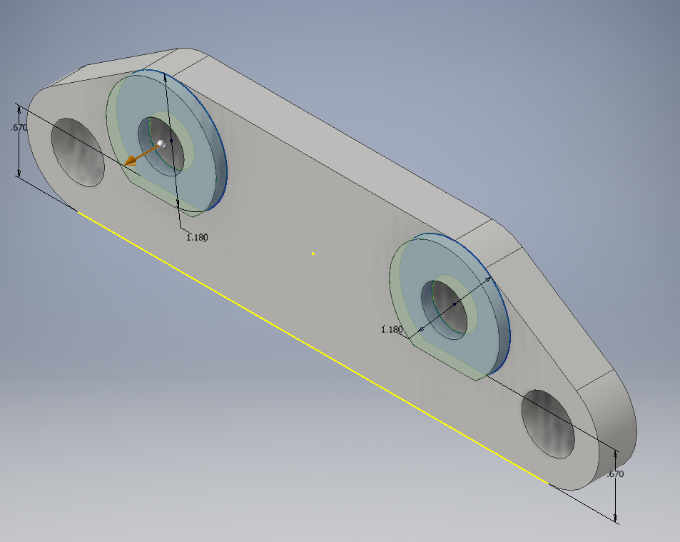
To start, I used the dimensions of the orthographic sketch to re-construct the base of the part.
|
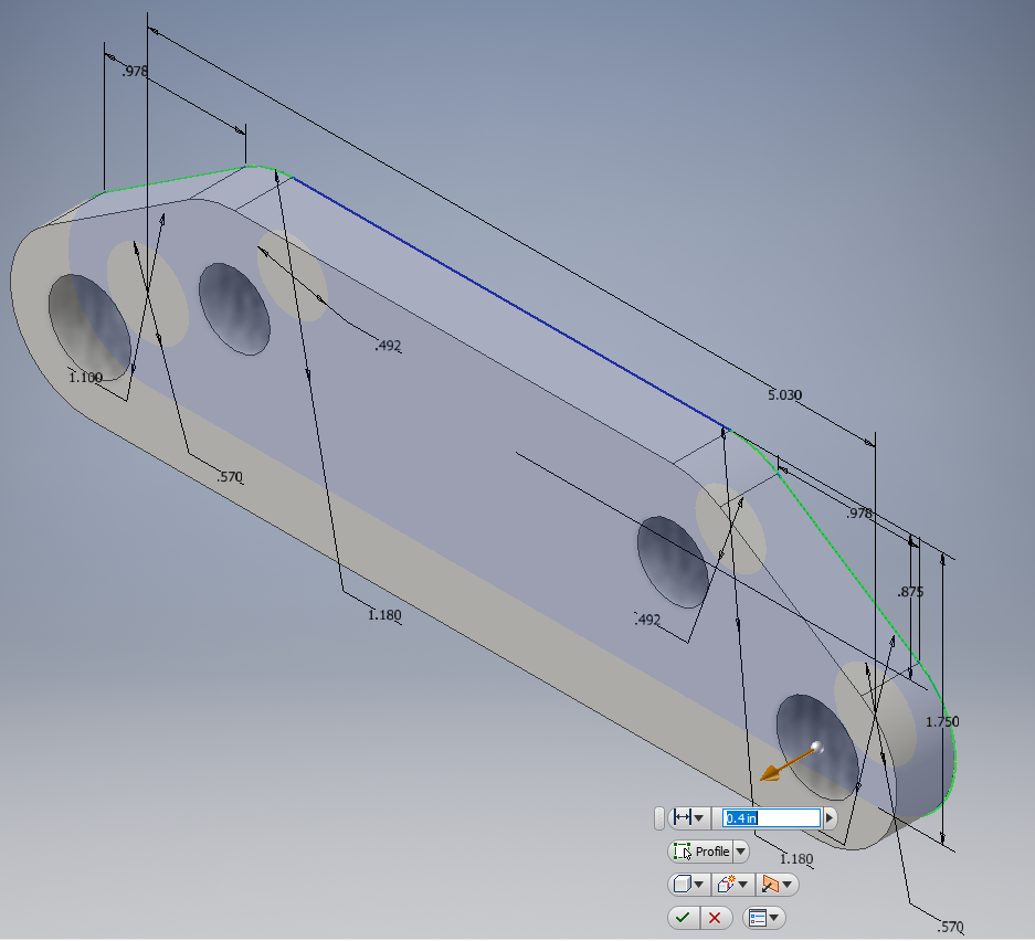
Next, I extruded the part to a height of 0.4 inches.
|
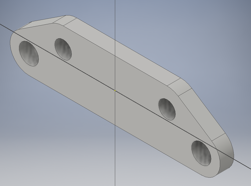
Here is the result of the first extrusion.
|
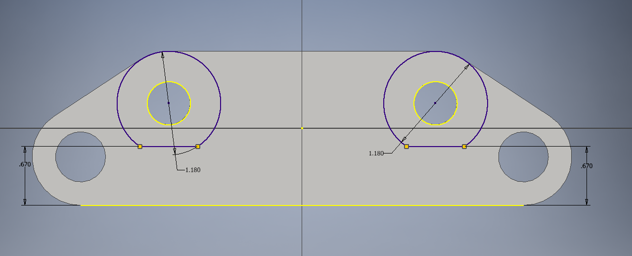
Then, I drew the second sketch with the 2 circles. To obtain the flat edge on the bottom, I drew a line over the circle, used the parallel function, and dimensioned the line to be 0.67 inches from the bottom. Finally, I trimmed the excess line, as well as the bottom curve of the circle.
|
Using simple math to subtract 0.4 inches from 0.51 inches, I extruded the 2 circles to a height of 0.11 inches.
|
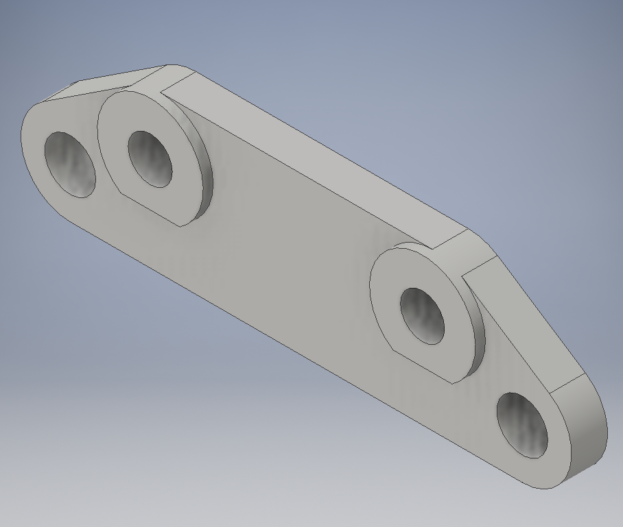
Here is the final 3-D modeled prototype race car brake bracket, ready to be converted in Fusion 360.
|
Working With Fusion 360
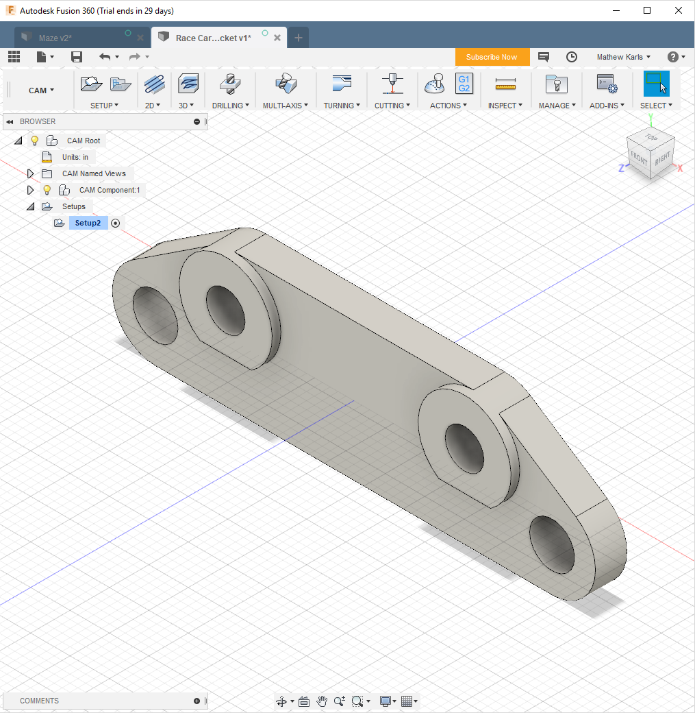
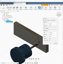
I started with Fusion 360 by uploading the brake bracket file, and by orienting it correctly.
|
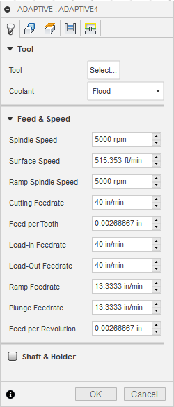
After specifying the stock restrictions, I adjusted the Tool: Select menu.
|
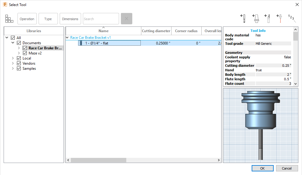
Since the tool was already made for the maze part, I simply copied the mill bit specifications over to the brake bracket.
|
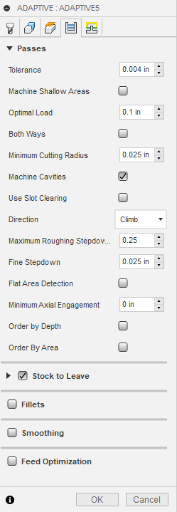
To finalize the milling procedure, I changed the maximum roughing stepdown to 0.25 inches, and the stock to leave to 0 inches.
|
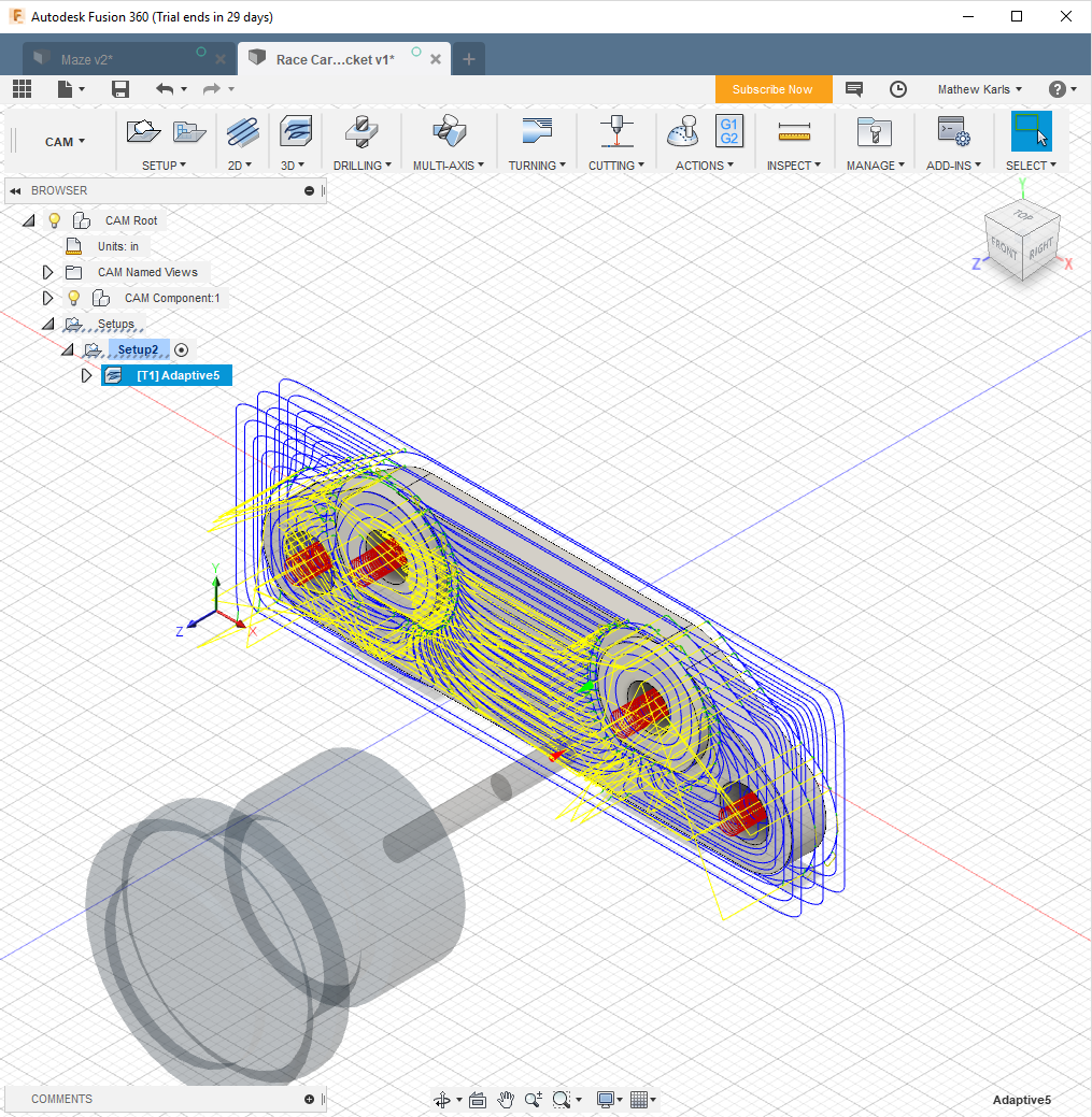
Next, Fusion 360 drew in all of the paths that the mill bit would take in order to shape the brake bracket.
|
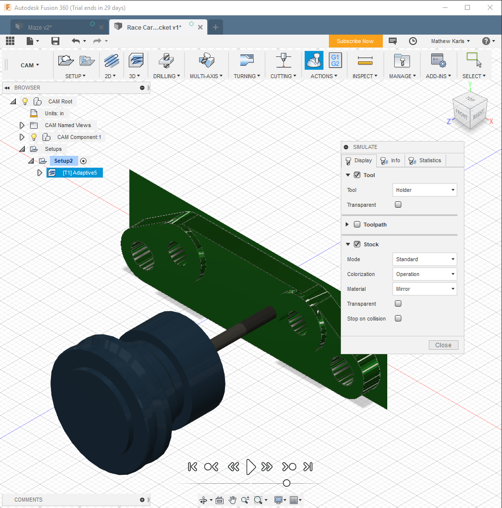
Then, I played the animation to determine how the part would be cut out on the CNC Mill.
|
This is the video in progress of cutting out the brake bracket.
|
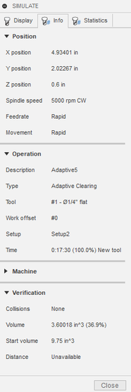
Finally, I checked under the simulation tab to figure out how long the part would take to be cut out on the router.
|
Using the CNC Mill Program
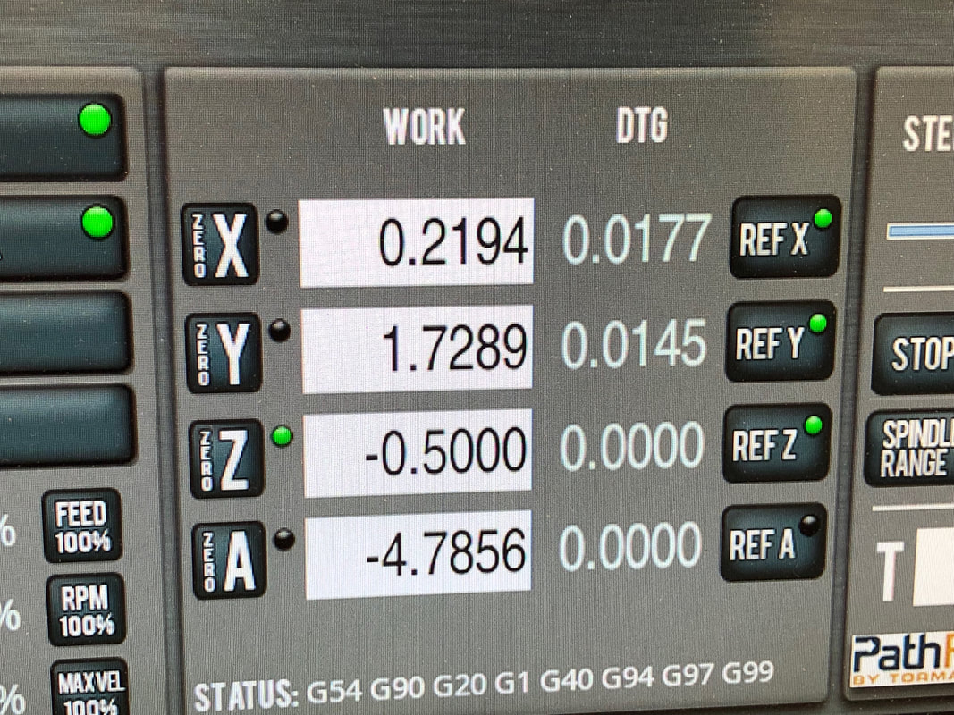
After I taped the brake bracket to the mill base, I referenced the x, y and z coordinate. I then aligned them to the corner of the foam piece and zeroed them.
|
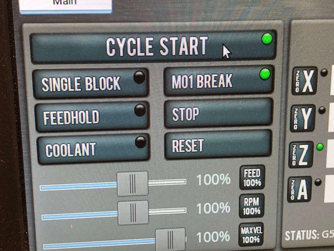
Then, I double-checked that everything was set up properly, I clicked that cycle start button
|
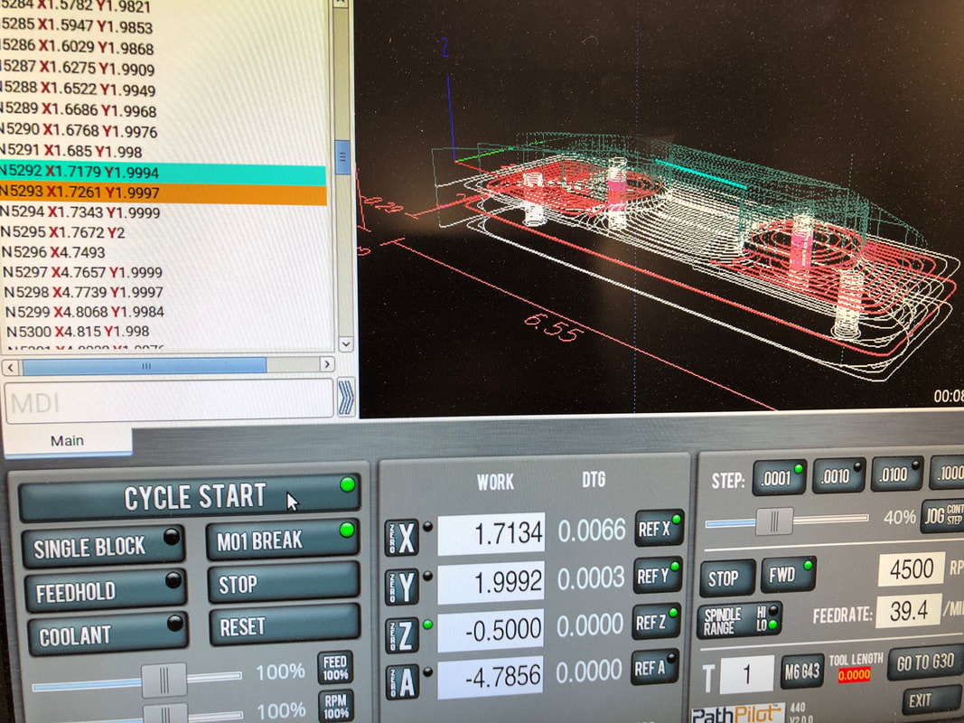
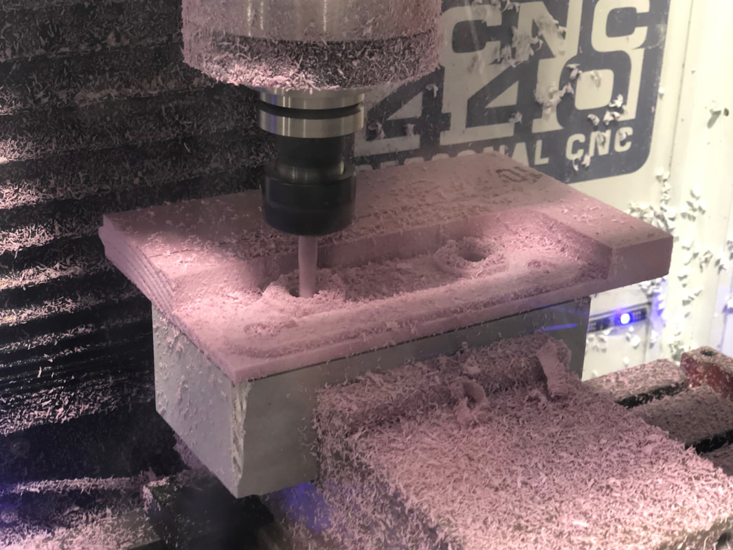
Here is an in-progress picture of the CNC Mill cutting out the bracket.
|
Using the CNC Mill
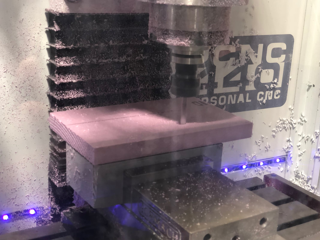
First, I taped and aligned the part to the CNC Mill base. Then, after I dertermined that the computer program was set up right, I clicked the cycle start button.
|
Here is the Mill cutting the preliminary layer of the brake bracket.
|
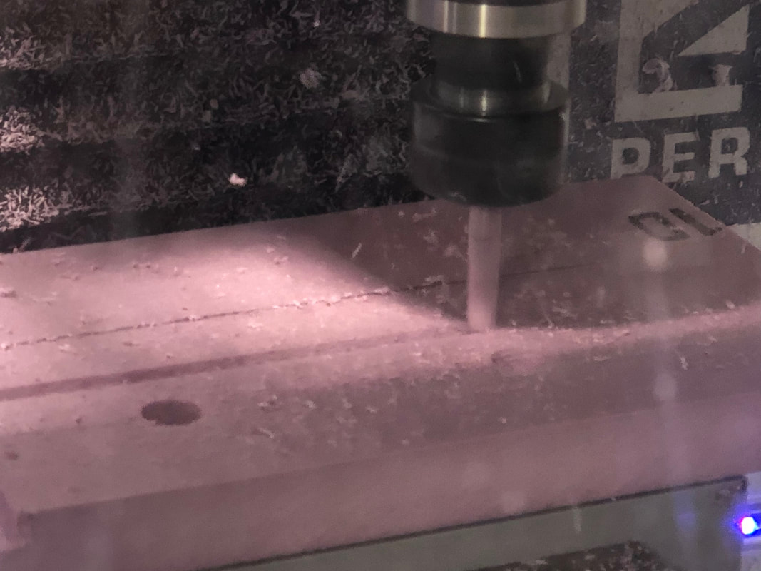
This is a picture of the Mill starting the secondary layer of the brake bracket.
|
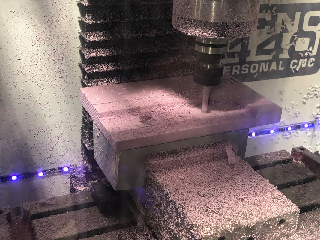
Here is the Mill finishing cutting out the bracket.
|
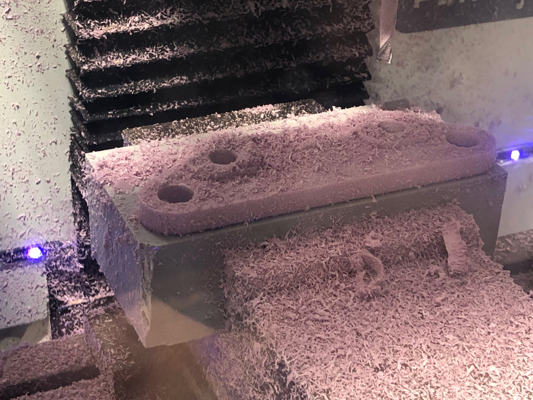
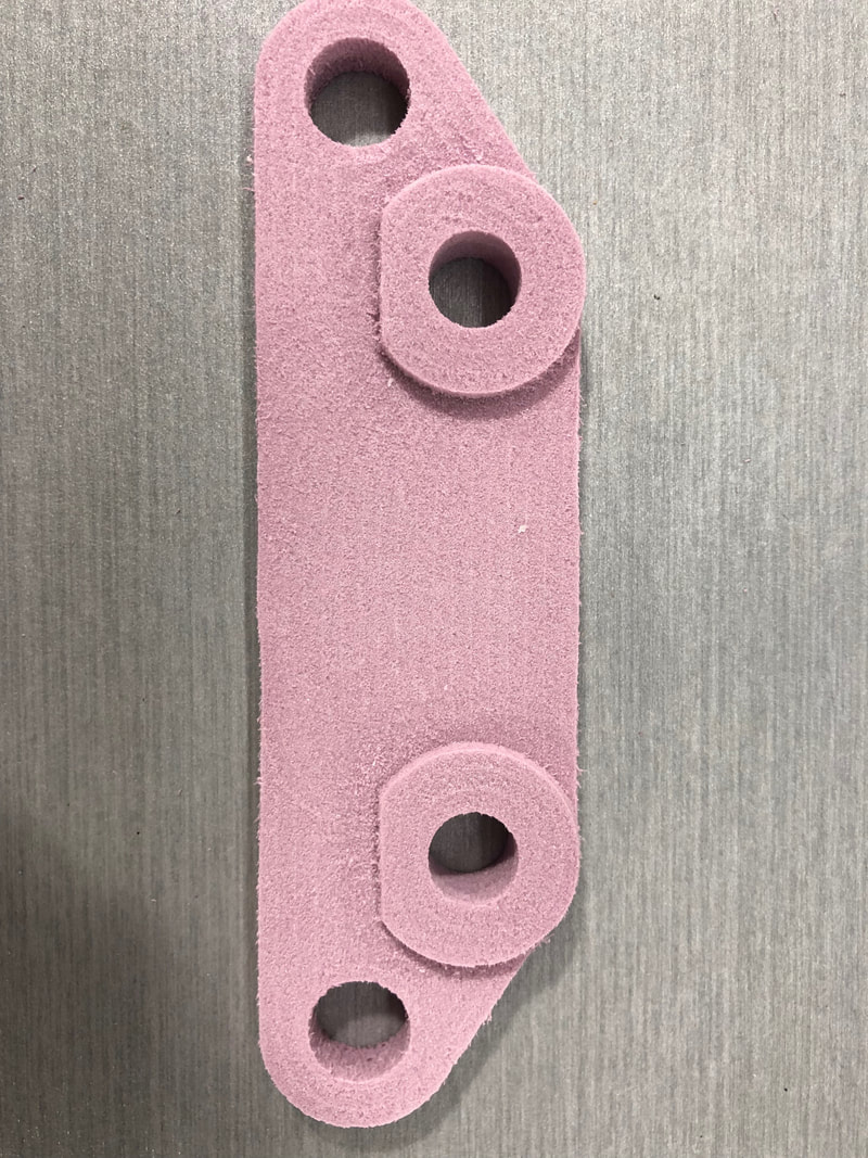
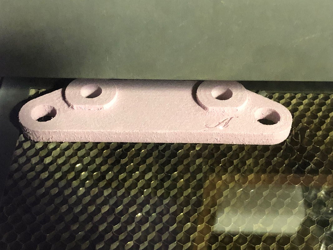
Here is the finished brake bracket on the Mill.
|
To edit, click on the text
and add your own words. |
Engraving My Name

To start, I designed my name in Illustrator, and changed the stroke weight and color to be correct.
|
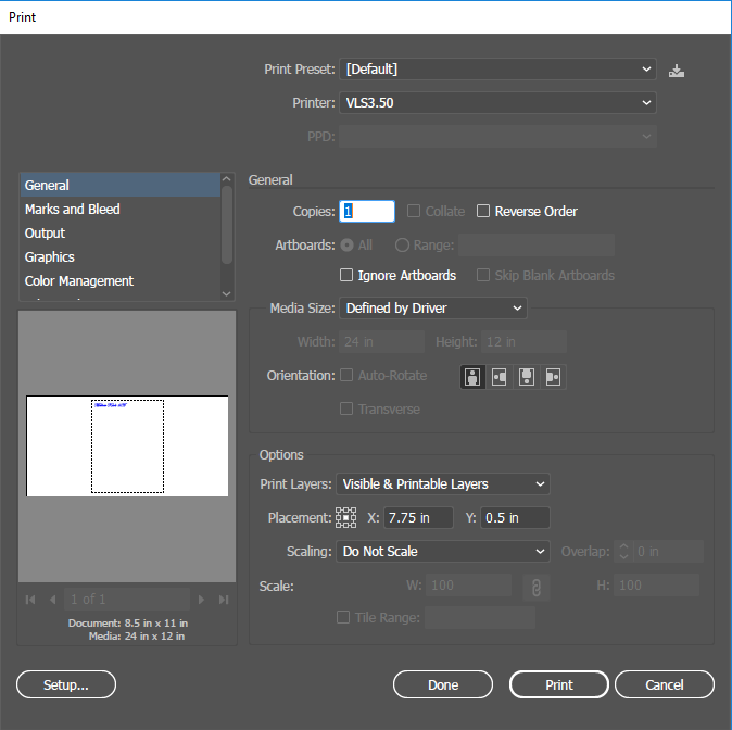
On the laser's computer, I opened the file and the print menu. I then clicked the Set-up button.
|
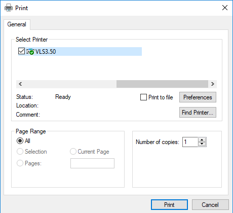
I selected the correct laser location, and opened the preferences menu.
|
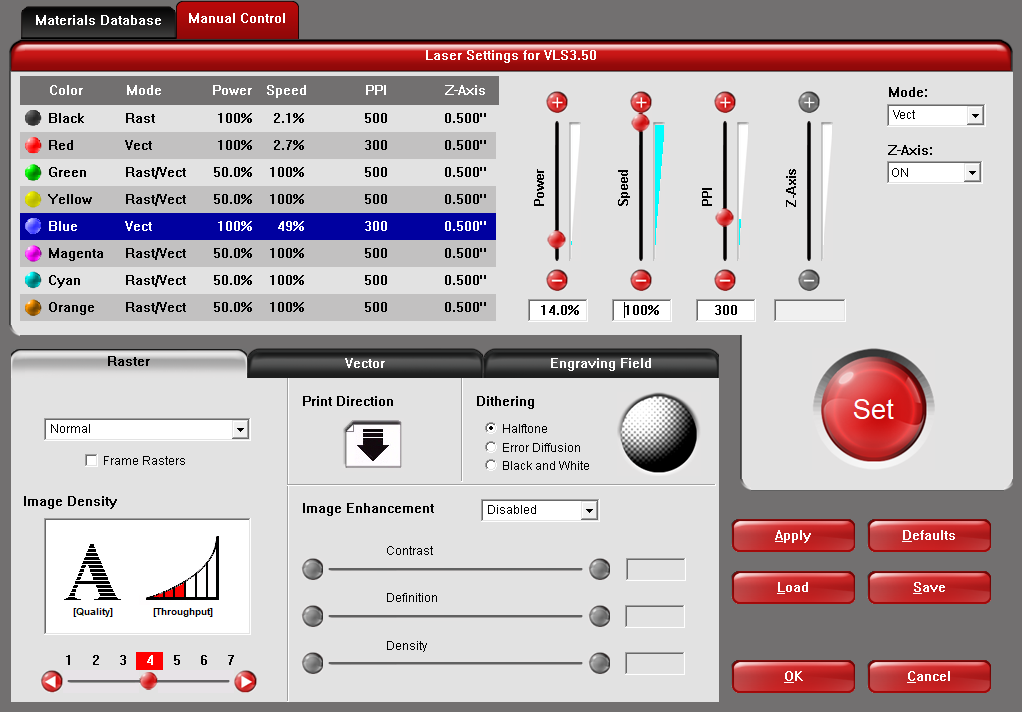
After I chose the material (Foam-Tool Foam), I selected the blue vector under the manual control tab and changed the power to 14%, and the speed to 100%.
|
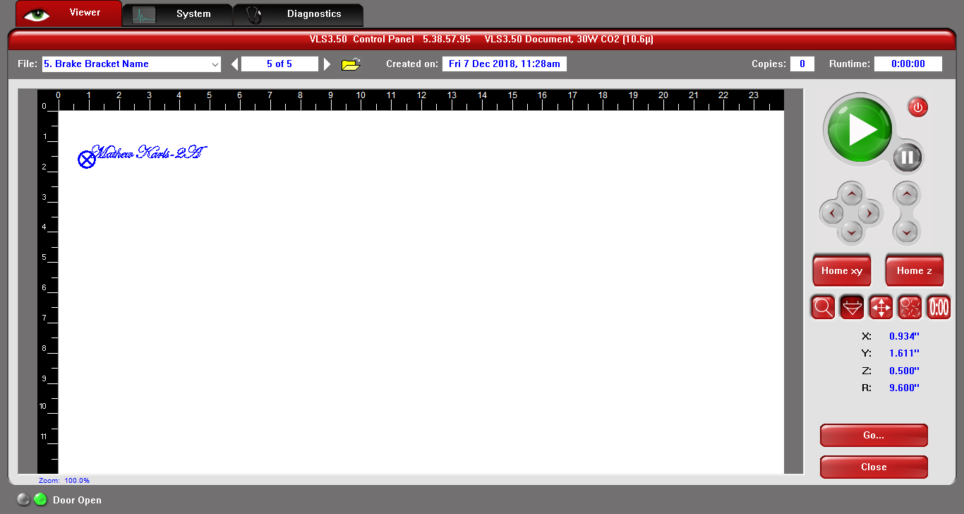
In the UCP program, I moved the file and double-checked that the laser wouldn't engrave off of the edge of the part.
|
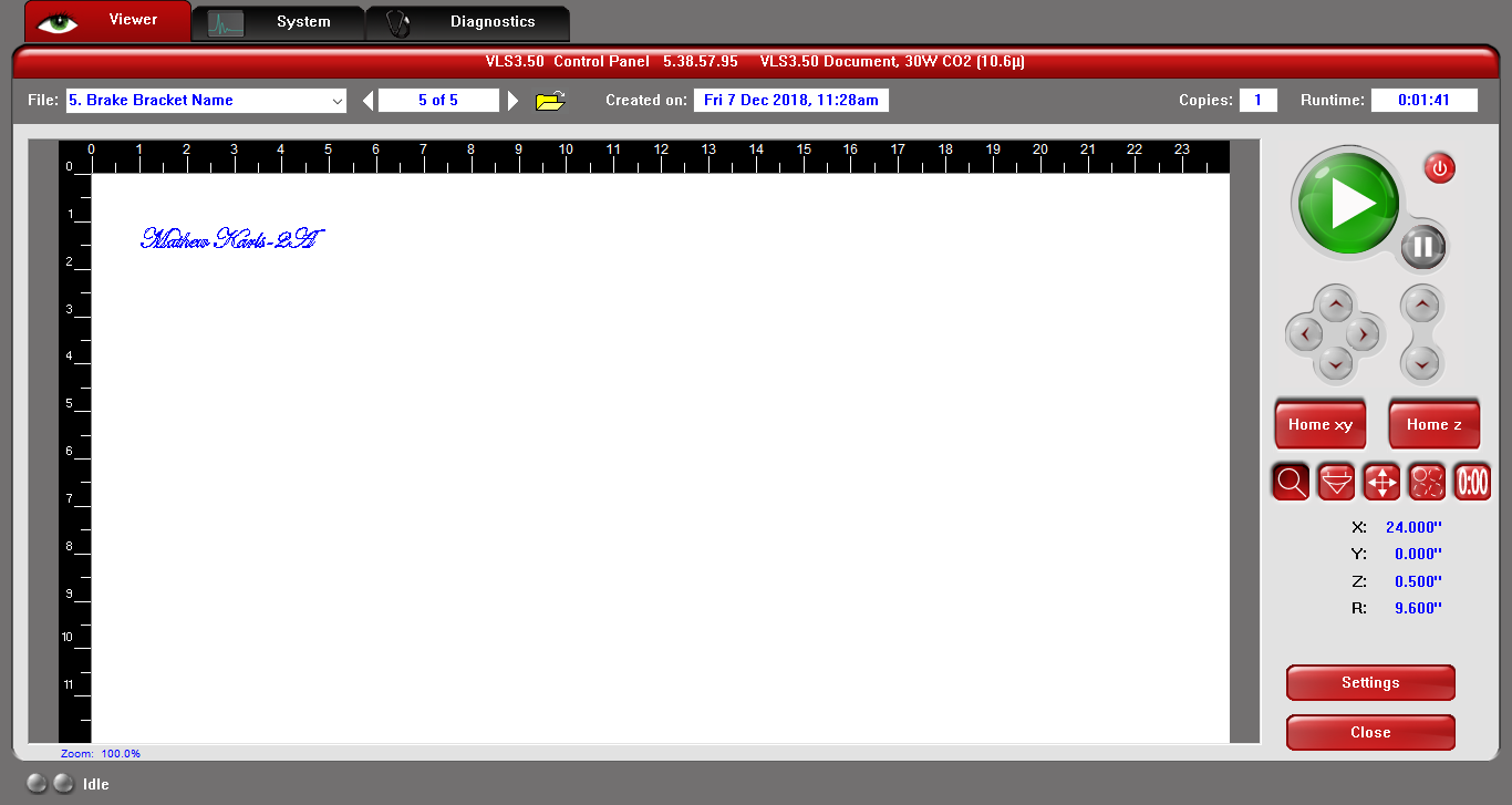
Finally, I made sure that everything was set up correctly, then I clicked the green play button.
|
Using the Laser
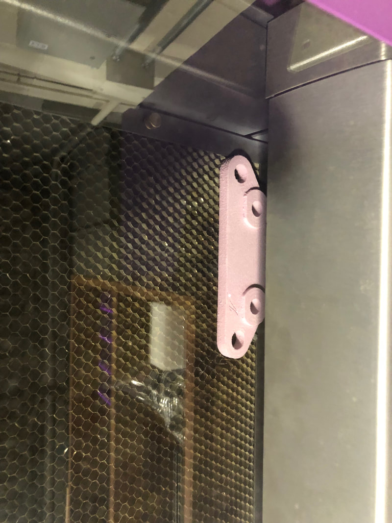
I first aligned the brake bracket with the edges of the laser bed. I started the laser after the file was positioned correctly.
|
Here is an in-progress picture of the laser engraving the brake bracket.
|
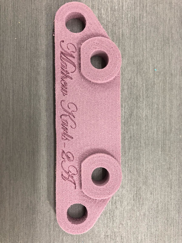
This is the final project: a milled race car brake bracket with my name laser engraved on it. I am very happy with the results of this project.
|
Summary
In this project, I gained a lot of knowledge. Most importantly, I learned how to accurately use the dimensions, the tangent function, as well as the concentric function to my advantage. As a result, I was able to quickly and accurately construct the race car brake bracket without too much trouble. In addition, I also learned how to use 3-D Adaptive Clearing in Fusion 360, as well as the various tool paths, to cut out the bracket in the most efficient manner. I also learned how to use all of the necessary parts of the CNC Mill to cut the brake bracket out of a piece of foam. Some of the most important examples include uploading the file and all of the lines of code to the program, referencing the coordinates, and using the circular controller to zero the coordinates. I also learned how to use the Manual Control tab under the Print Menu to make the laser understand how to engrave the blue vector line. Overall, I am very happy with the way this project turned out, and I know that the knowledge I gained from this project will certainly benefit my final project.
