Beginning Concepts
|
|
|
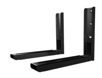
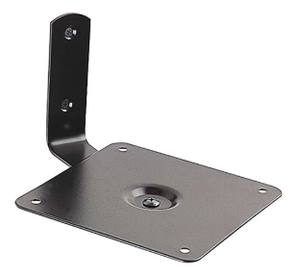
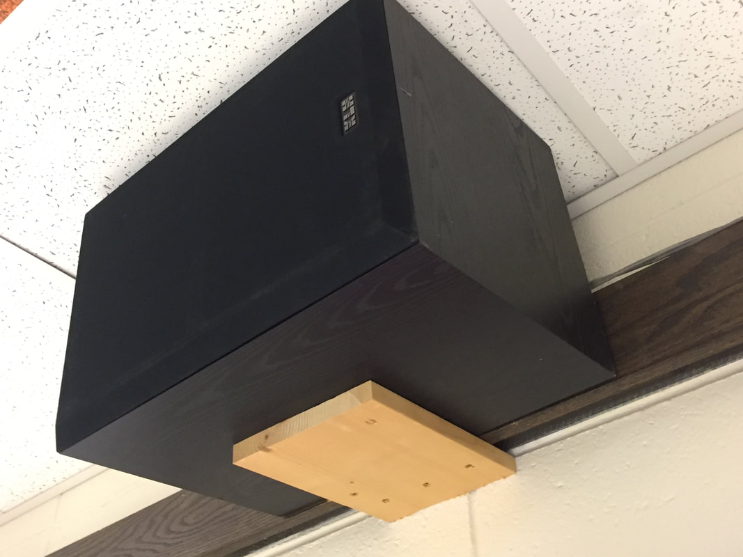
I started this project by researching existing speaker brackets, as well as solutions to improve the speaker's current bracket. The photo on the far right is the current speaker bracket, which needs to be improved due to the speaker's listing from the wall.
|
|
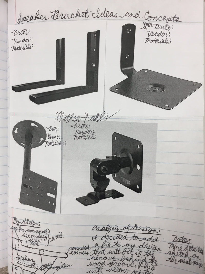
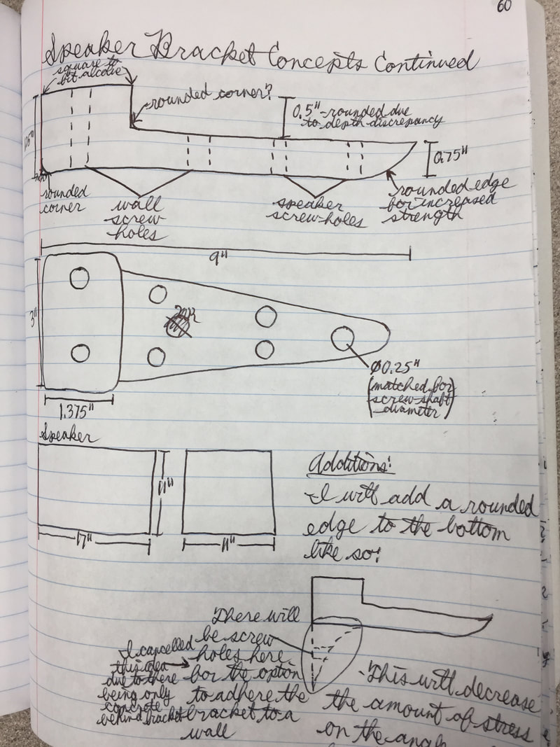
These are pages from my designer notebook regarding the research and development of my redesign project. They show pre-search for the project, specific constraints and criteria, as well as the final design of the product.
Creating The IDEA
|
|
|
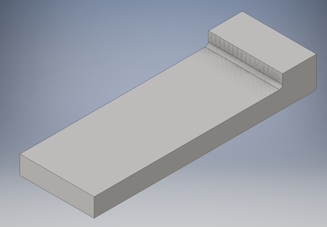
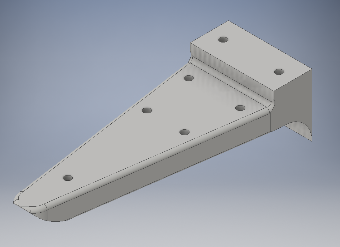
I started creating the redesign project in Inventor. I first made a square block shape, then extruded out and cut rounded edges off of the corners to make a more aesthetically appealing bracket. I then planned and cut holes in the bracket for the screws to mount it. The back two rows of screws attach to the wood trim, while the front two rows attach to the speaker for limited movement.

|
|
|
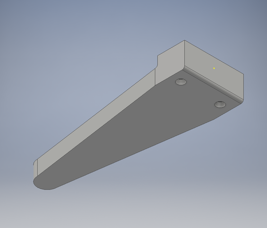
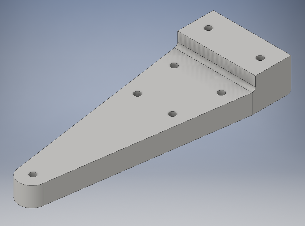
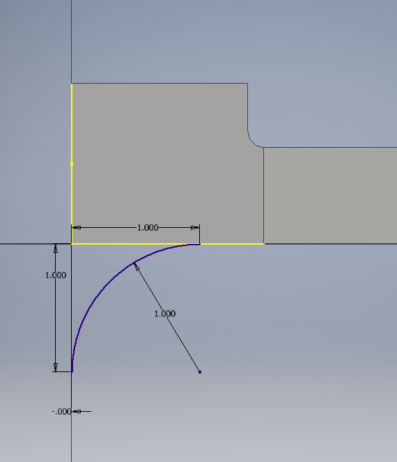
Next, I rounded the front edge to increase its structural integrity in supporting the weight of the speaker. I then added a rounded curve on the bottom of the bracket for extra wall bracing. I finally rounded the showing edges of the bracket, keeping the alcove and wall sections' corners square.
Preparing The Design For Printing
|

|
|
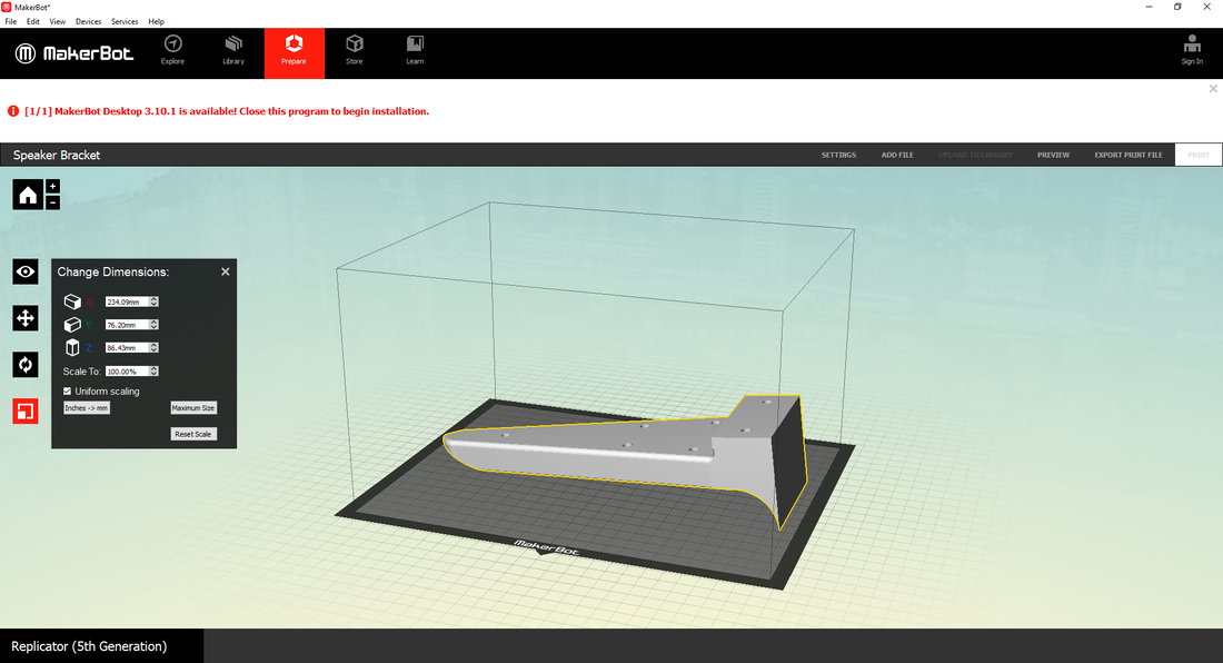
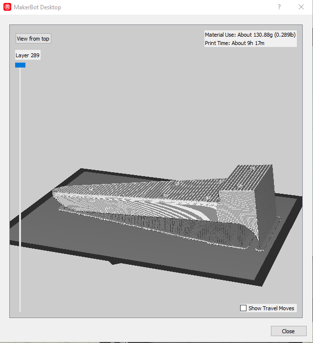
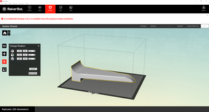
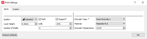
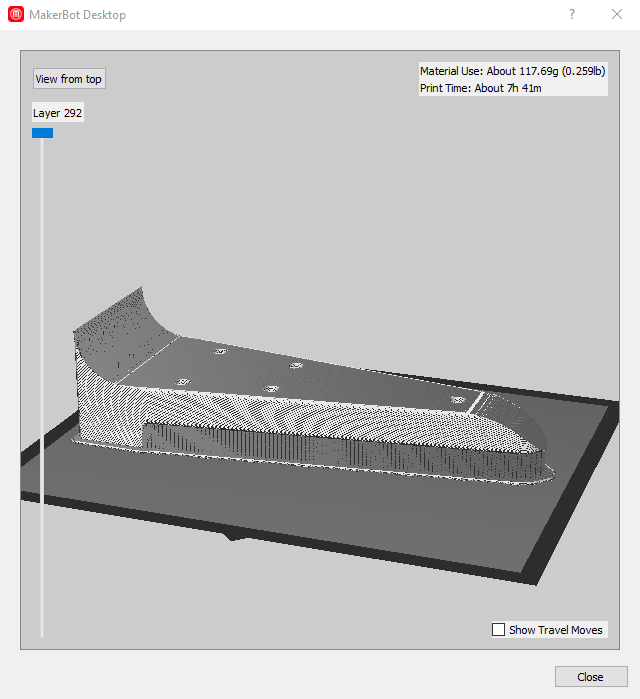
After I finished designing the bracket in Inventor, I converted the file into an STL file. Next, I checked the 3-D printer settings to match what I needed, and that I had supports in my print. Before I transferred the file to my flash drive, I previewed the file to make sure that all of the layers would be printed correctly.
Printing The Bracket
|
|
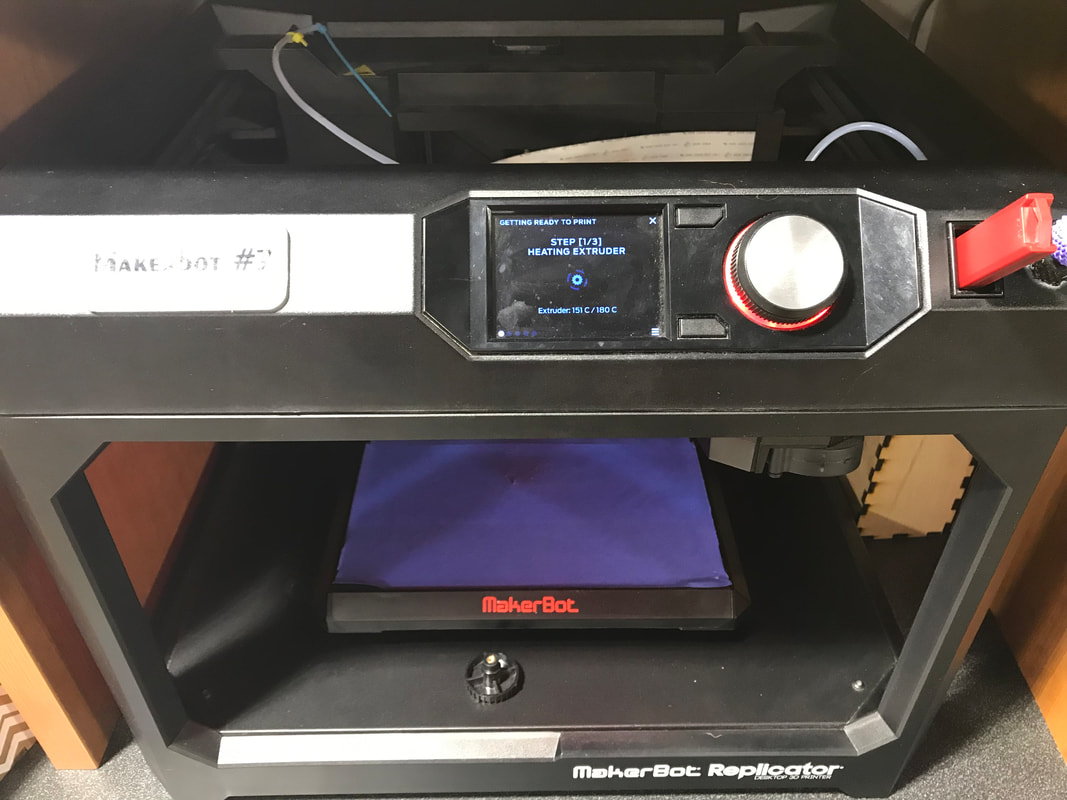
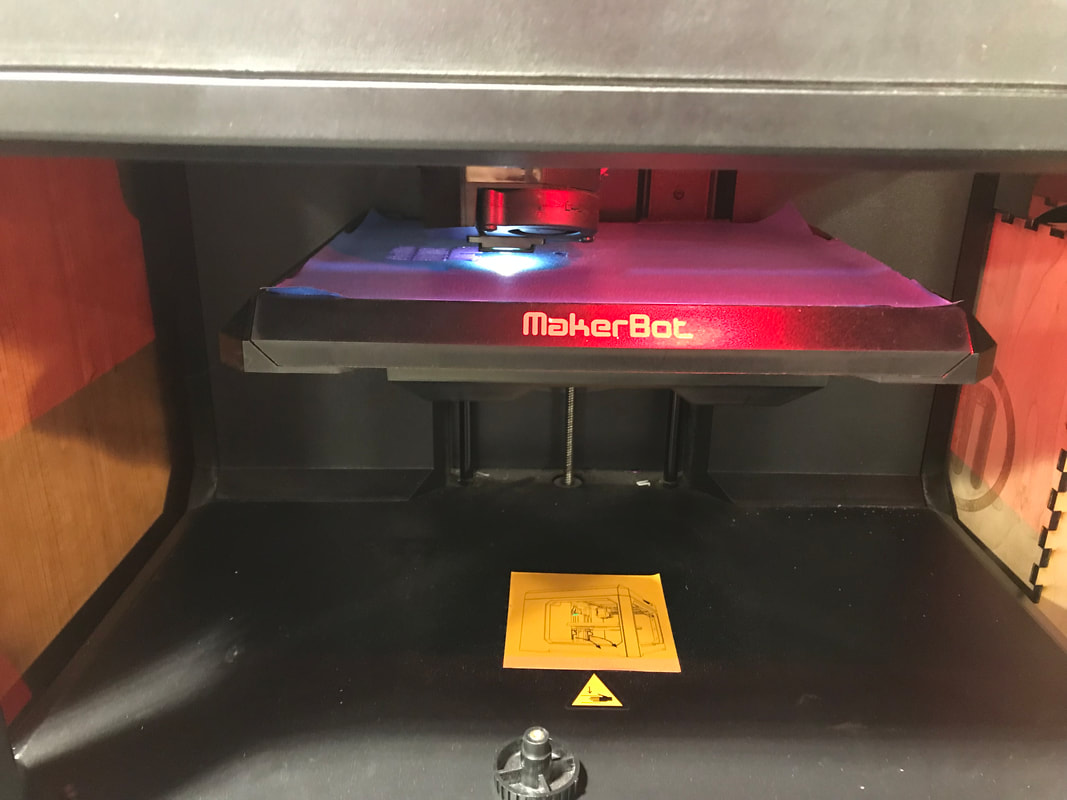
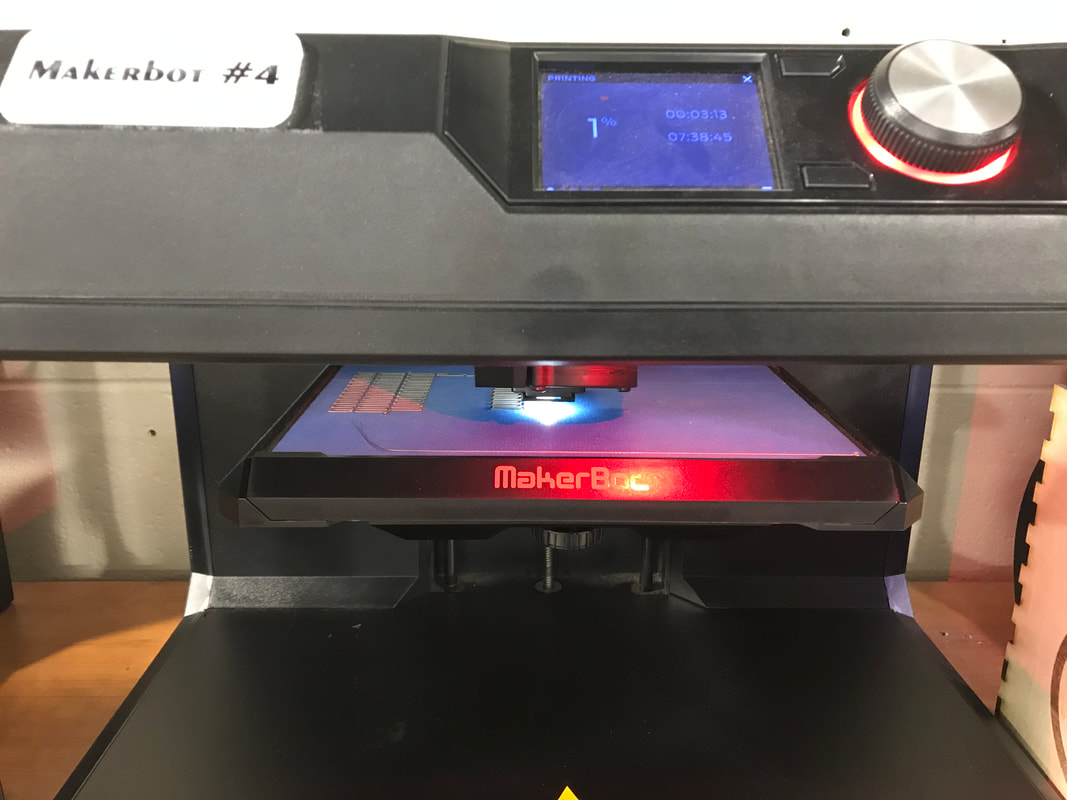
Once my design was finalized, I transferred the MakerBot file to a MakerBot 3-D printer. I waited until the raft was finished printing, so that I could verify that the print would be constructed correctly. The picture on the right is the 3-D printer setting up the raft for the construction of the speaker bracket.
Finalizing The Bracket
|
|
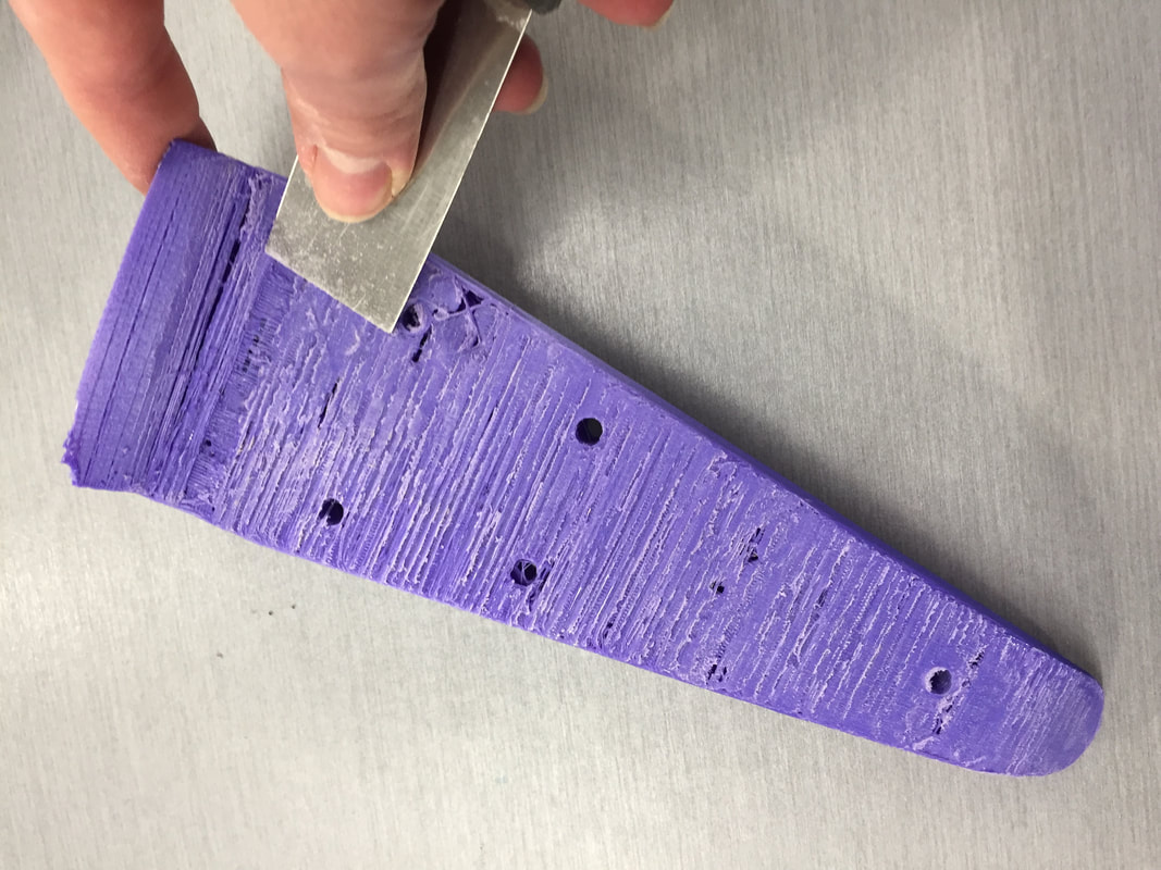
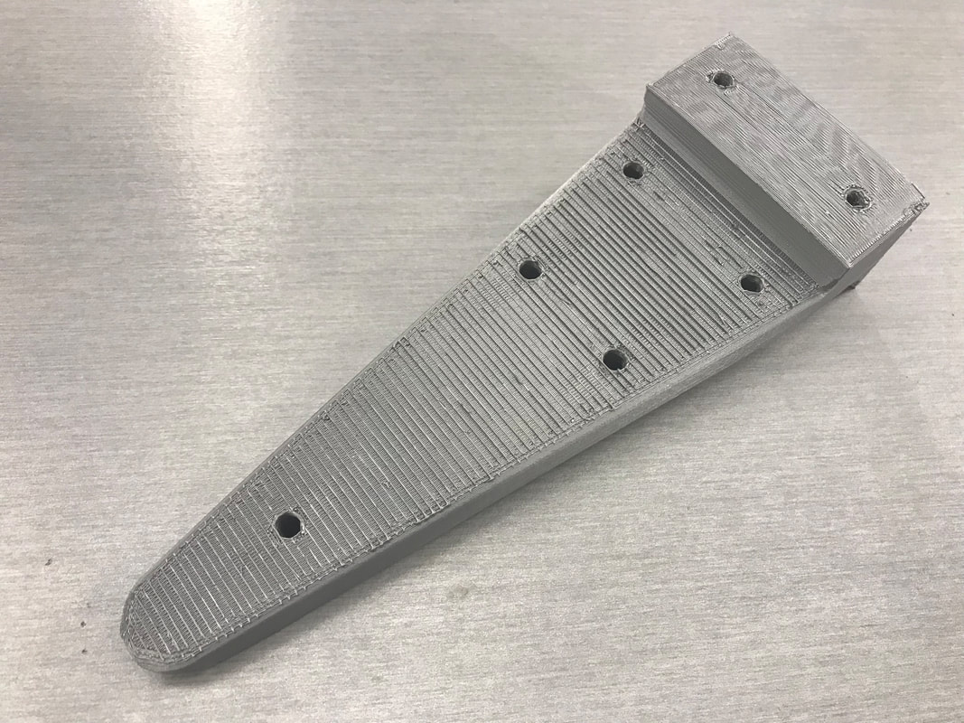
Finally, I finished preparing the bracket for evaluation by using a combination of the chisel, the orbital sander, and the handheld sander to smooth down the rest of the rough edges left by the supports from the 3-D printer. What I feel could be fixed and improved for future prototypes that I find a better way to remove the supports, and a better way to make sure the curve underneath is printed correctly. The photo on the far right is the first prototype of the speaker bracket, ready for testing.
Improving The Bracket
|
|
|
Although my first speaker bracket was satisfactory to the constraints and criteria, I knew that it could be improved. I realized that most of the bracket's problems came from the position that it was printed in, so I started there. I oriented it upside down, as I wanted the bottom side to be clean from supports, and because the top side would be the flattest side to print on. After I double-checked that the settings were correct, I then saved the design to my flash drive once more.
Reprinting
|

|
|
After I finished re-orienting the bracket and saving it to my flash drive, I started the print on a MakerBot for the second time. Overall, the printer took only 7 hours to print the bracket rather than 9 for the first prototype. This is probably due to the fact that the MakerBot had to print less supports, and because the part was oriented to the flattest face available.
Finalization of the Second Prototype
|
|
|
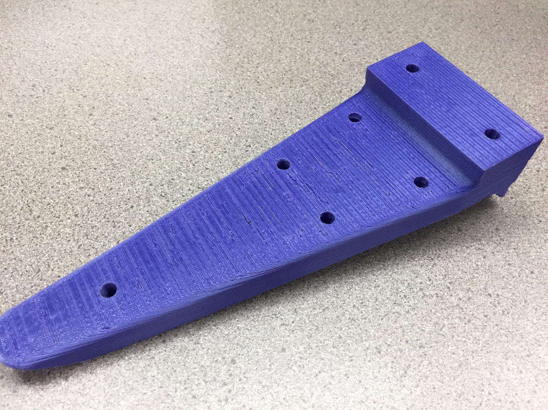
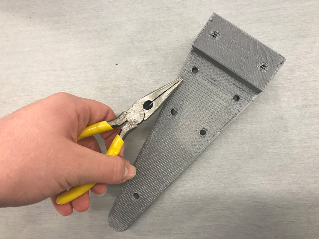
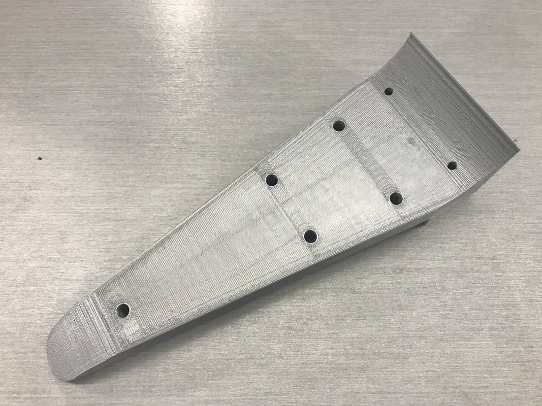
Once the bracket was finished printing, I used pliers to remove the supports from underneath it. Since the bottom back two holes were covered up, I used a drill with a small bit to pre-drill the hole so the bracket can be easily mounted without any hassle in the future. The picture in the center and on the far right is the second prototype of the speaker bracket, ready for testing.
Summary
In the course of this project, I learned a lot of valuable lessons and tricks to ensure the best outcome for a project like this one. First and foremost, I learned how to redesign a product to better fit the needs of the situation, such as using the original product's surroundings to increase the safety and stability of the speaker brackets. I also learned how to use more features in Inventor, such as using an instant 2-D arc tool to draw rounded corners on my design. I also learned how to fix the problem of a lack of holes on my project by pre-drilling them with a small drill bit. Finally, I learned through trial and error how to become more efficient with supports on a 3-D print, and how to effectively get rid of them after the print is done. Some methods I used included chiseling, as well as sanding them off, and using a pair of pliers to pull off the remaining pieces. By learning these important ideas, I know that I will be able to use these new ideas to complete my semester project more efficiently, more effectively, and more creatively.
