Making the Crucial Choice
|
|
|
|
|
|
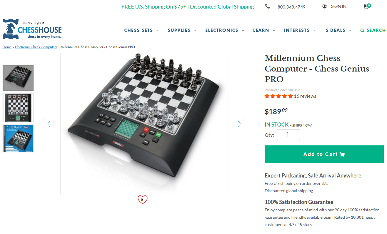
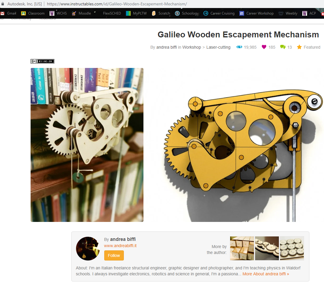
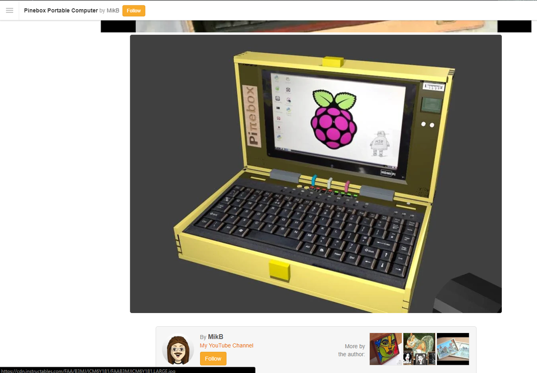
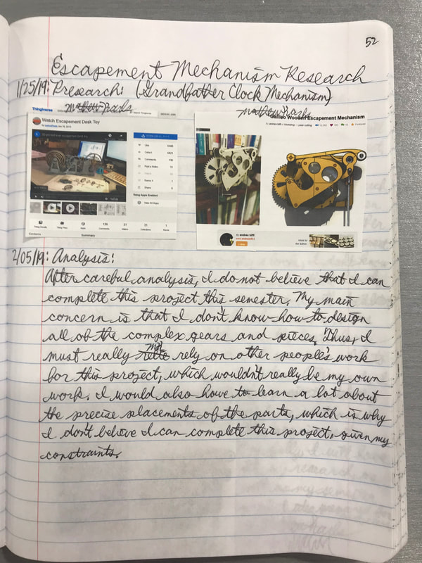
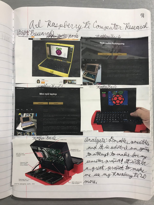
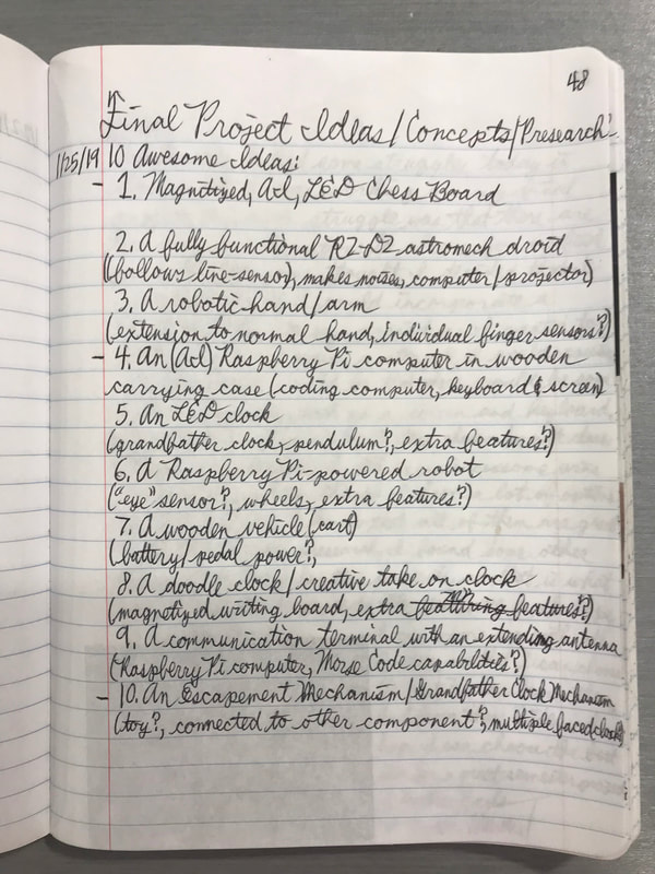
For this project, I had to do a lot of research and preliminary work. First, I had to decide even what I wanted to make this semester. I made a list of my top 10 ideas, then I narrowed it down to my final 3. They were a magnetized, AI, LED chess board, a grandfather clock mechanism, or a Raspberry Pi 2.0 Computer with wooden carrying briefcase. I chose to make the Raspberry Pi Computer, so that I would have the opportunity to work with my Raspberry Pi 2.0 more.
Preliminary Planning
|
|
|
|
|
|
|
|
|
|
|
|
|
|
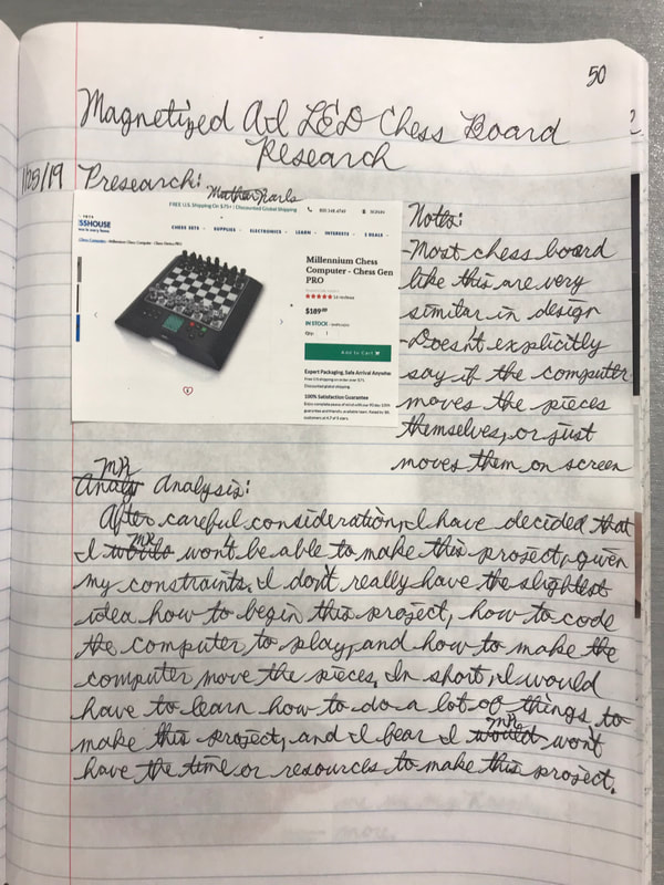
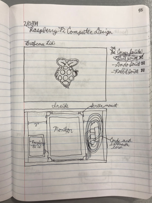
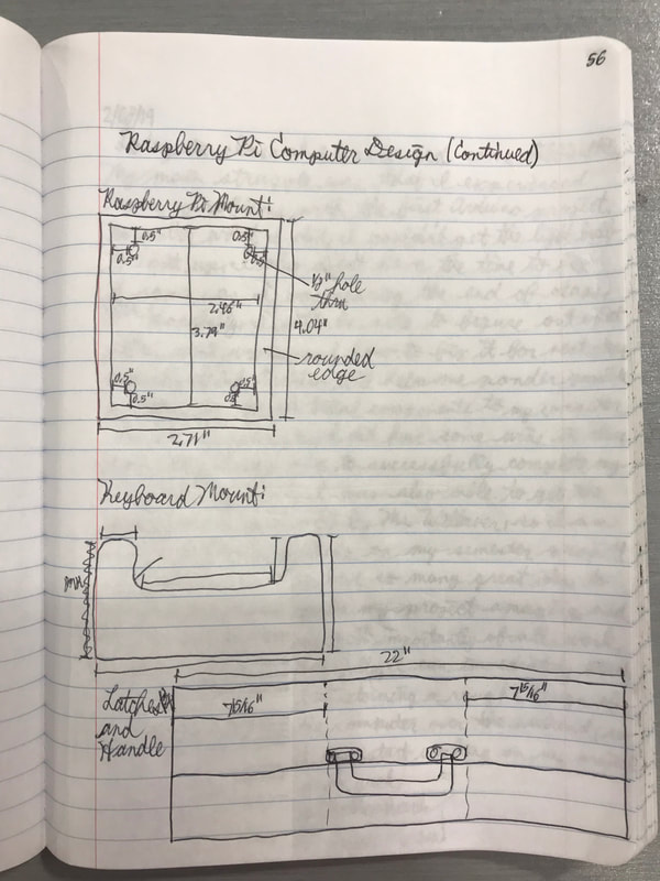
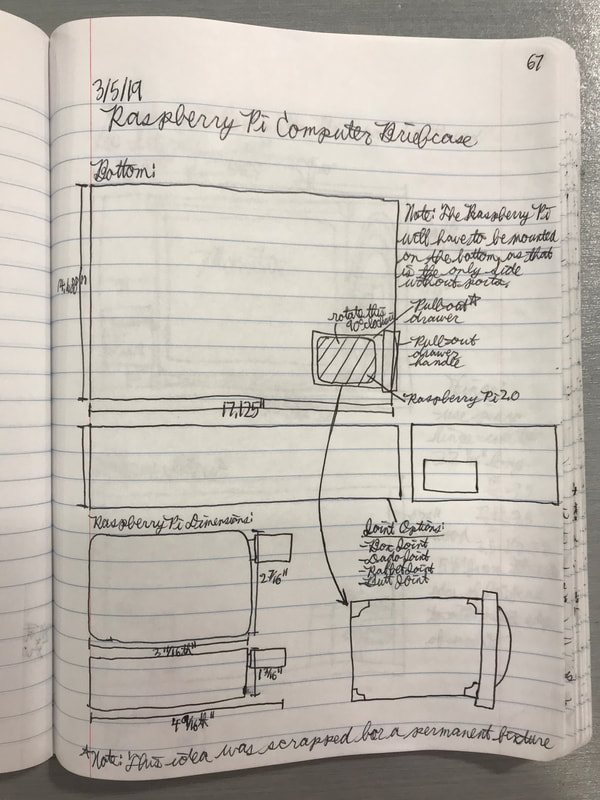
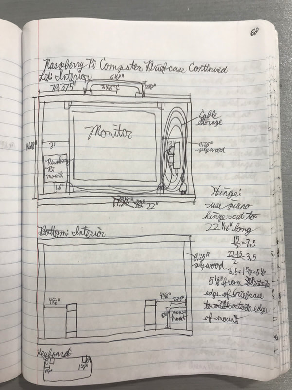
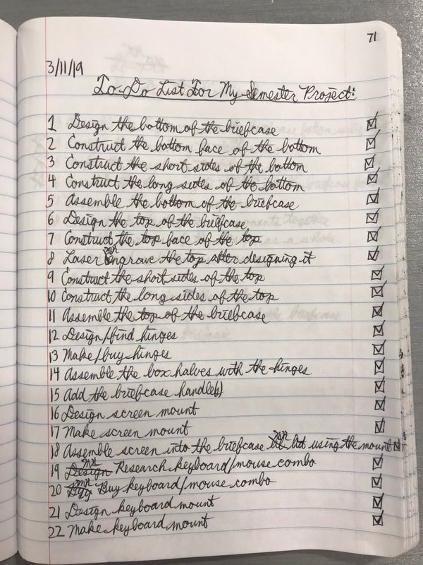
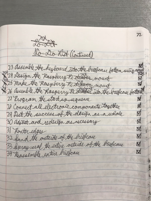
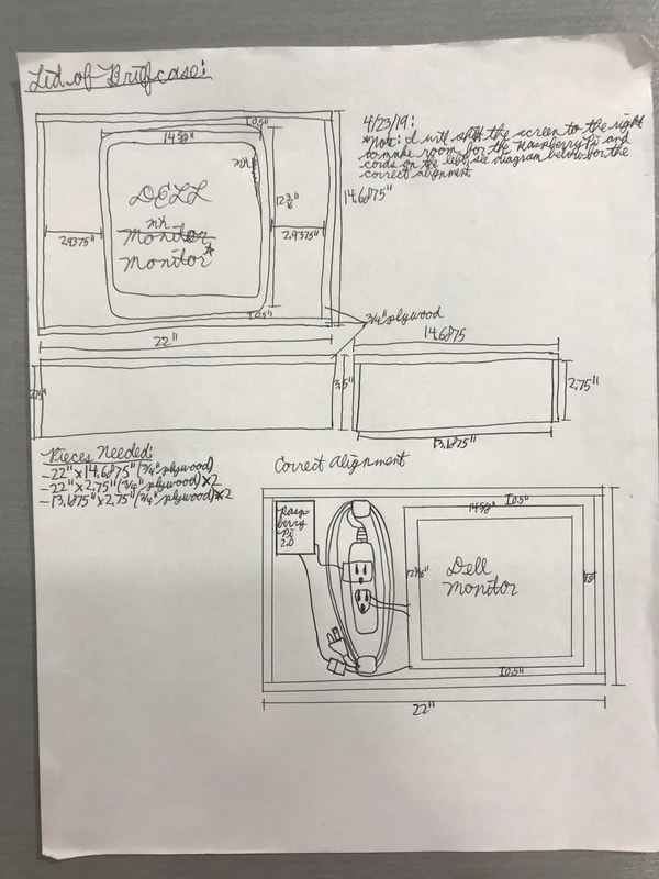
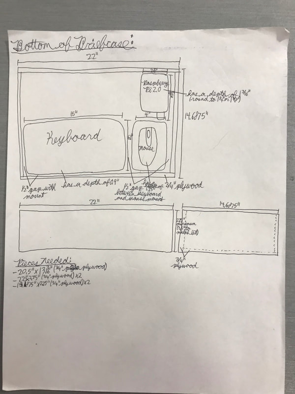
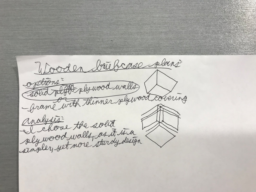
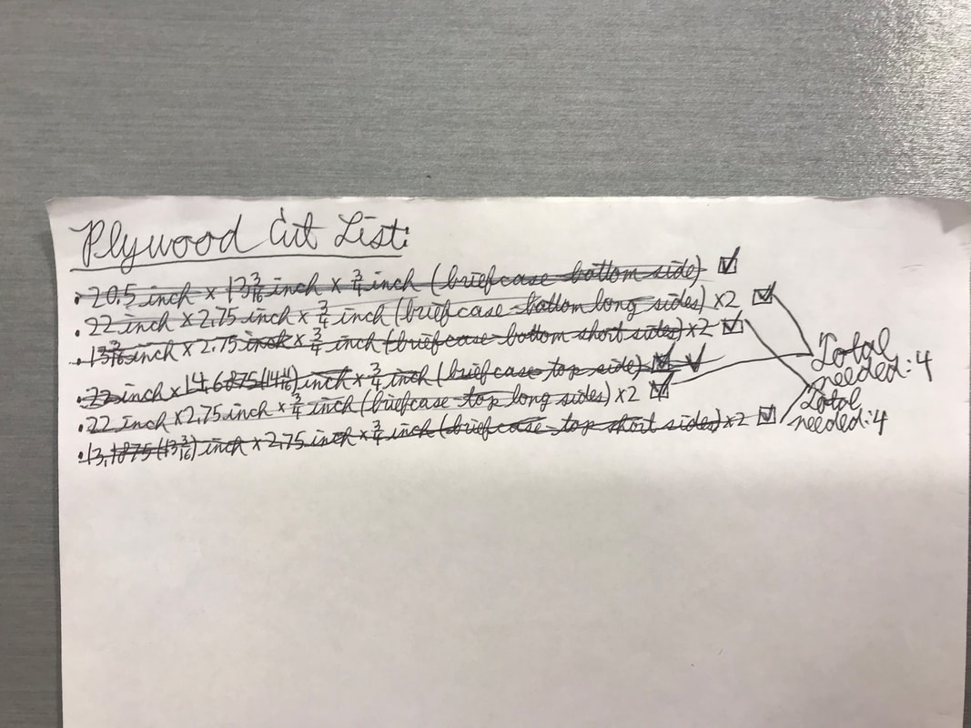
With my semester project idea chosen, I got straight to work, researching every aspect that I would need to design, create, and assemble. These are pages from my Designer Notebook explaining the research that I undertook, as well as the specifications for every part of my project. All this research and planning was needed before I could even begin the project itself.
Making the Case
|
|
|
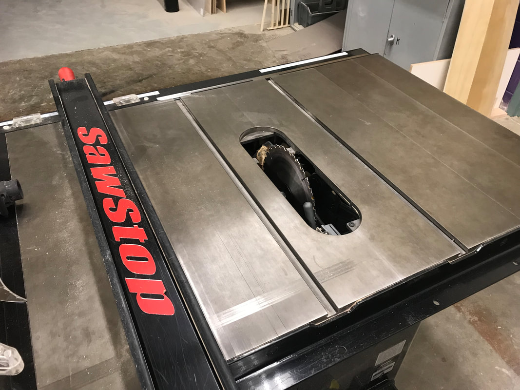
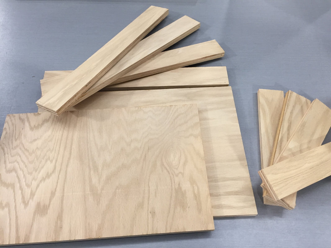
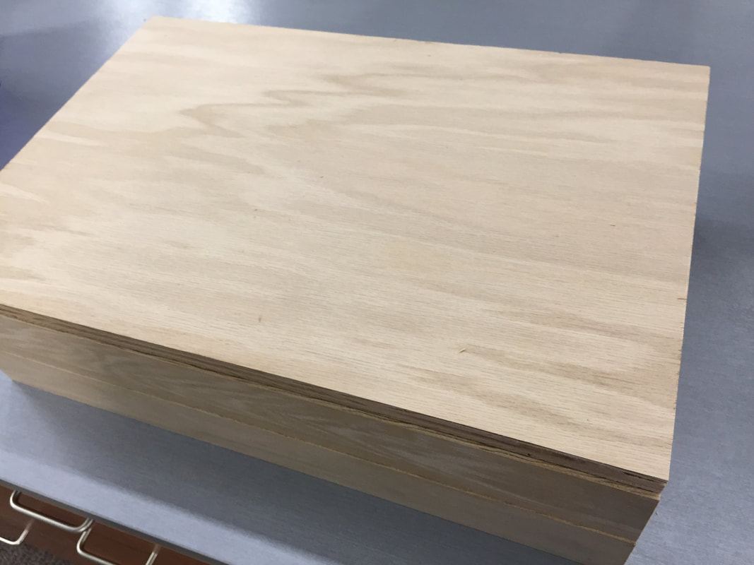
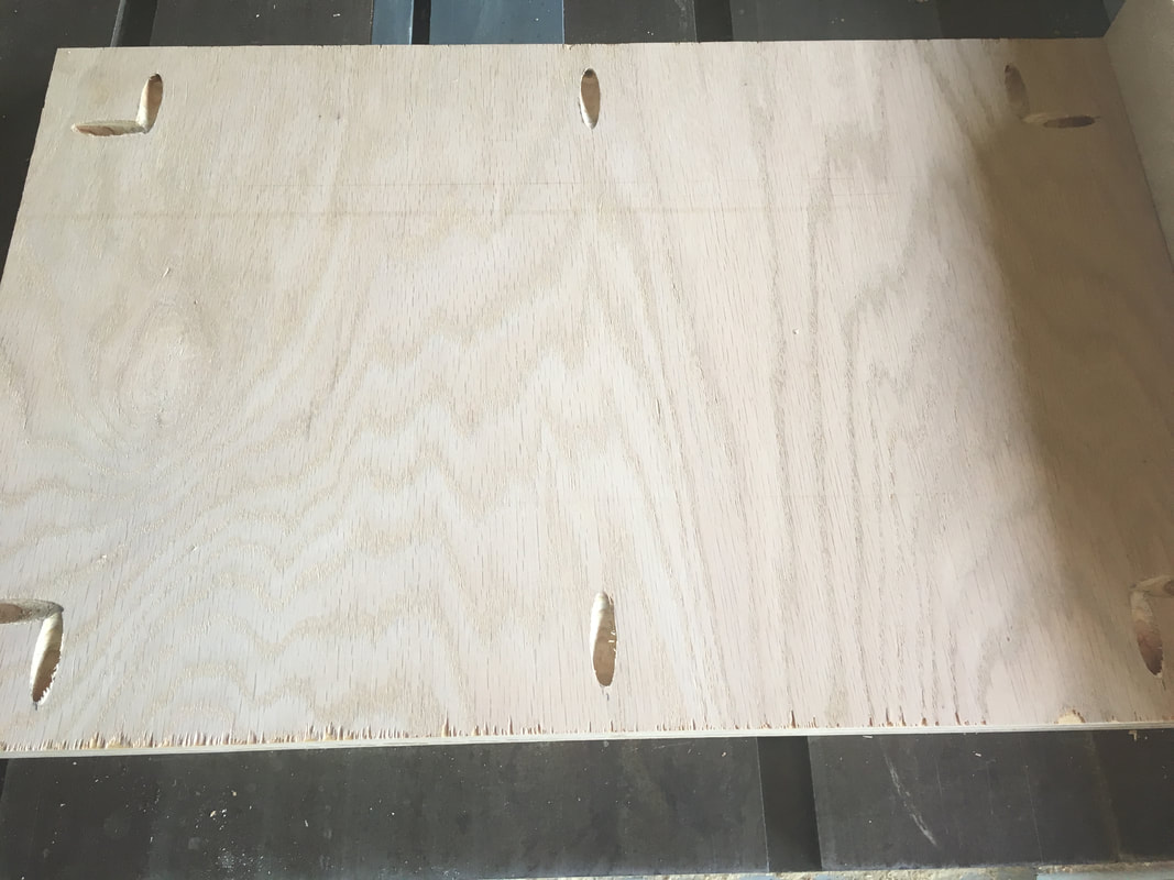
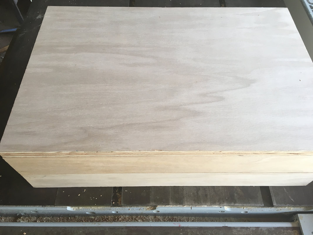
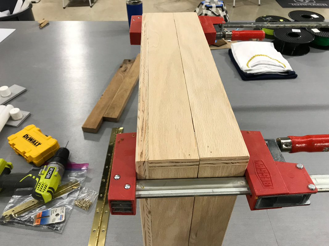
The first major piece of my semester project was to create the outer shell of the computer, so I started there. With Mr. Willauer's help, I was able to use the table saw in the Woods Lab to cut out the ten pieces I needed: 4 long edges, 4 short edges, 1 top face, and 1 bottom face. Afterwards, I roughly lined up the edges of the case halves to determine how accurate they were, as shown in the second picture. Fortunately, they were perfect, so I was able to continue.
Assembling the Halves
|
|
|
|
|
|
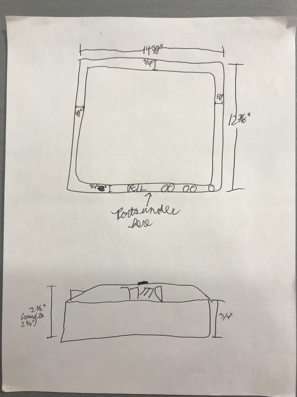
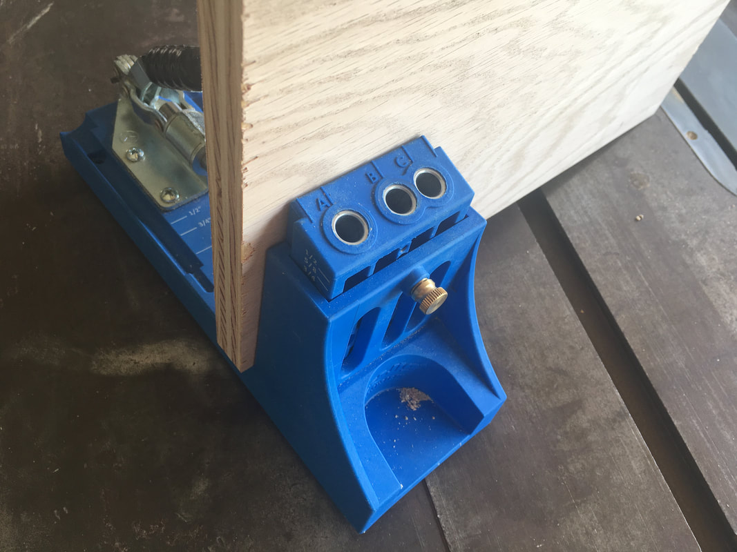
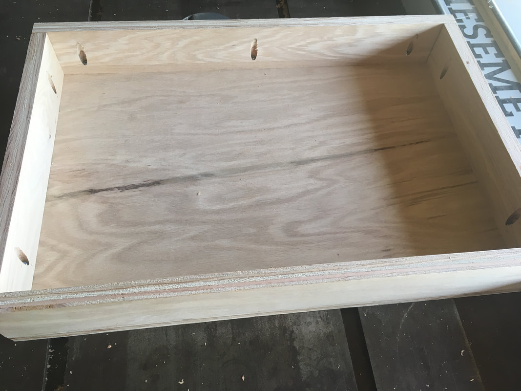
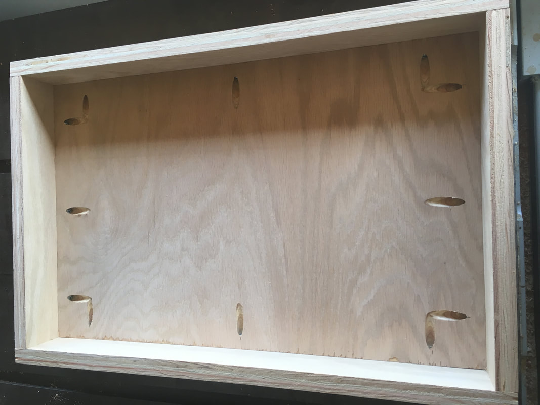
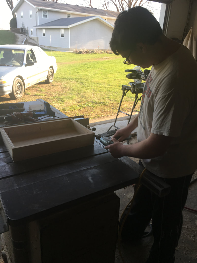
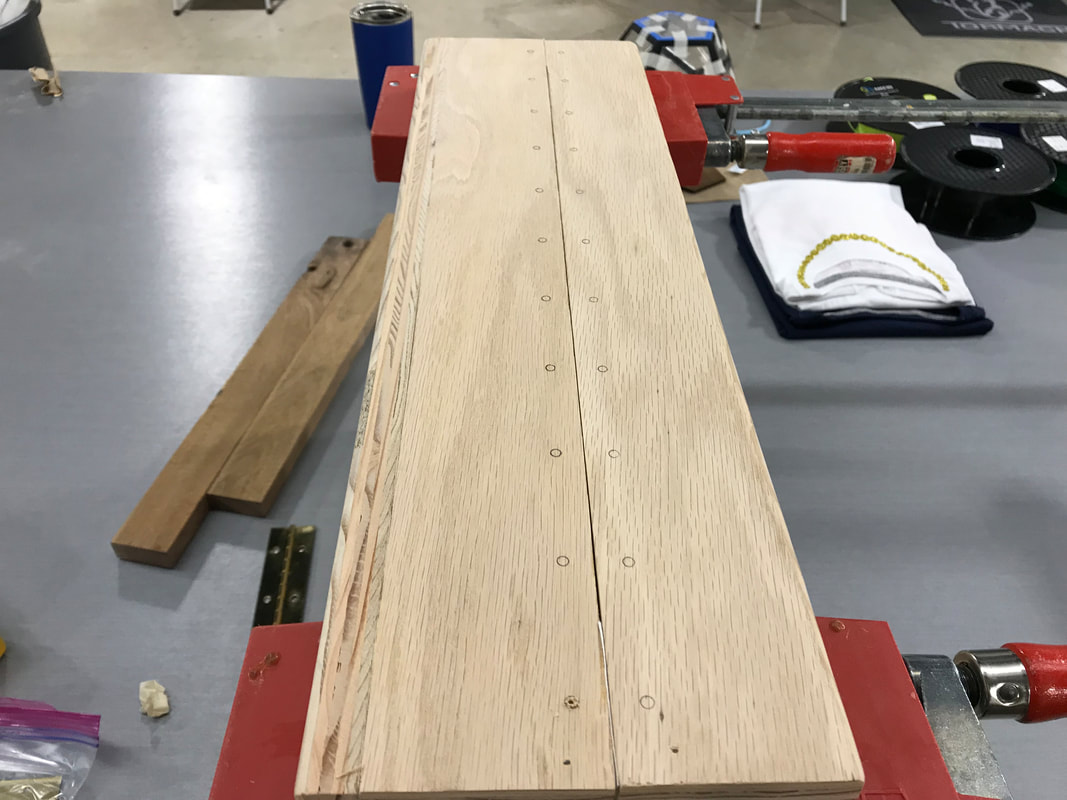
Over the weekend, with the help of my dad, I assembled the halves of the briefcase. I used a Kreg Jig to pre-drill the holes on the parts, then I screwed the screws in, creating two very structurally sound box halves. A couple of air nails in either end of the sides where they overlapped, and I increased the structural integrity of the halves even more. I then brought them back to the Innovation Center, and started taking measurements that would later help the creation of my other parts.
Building the Mouse Mount
|
|
|
|
|
|
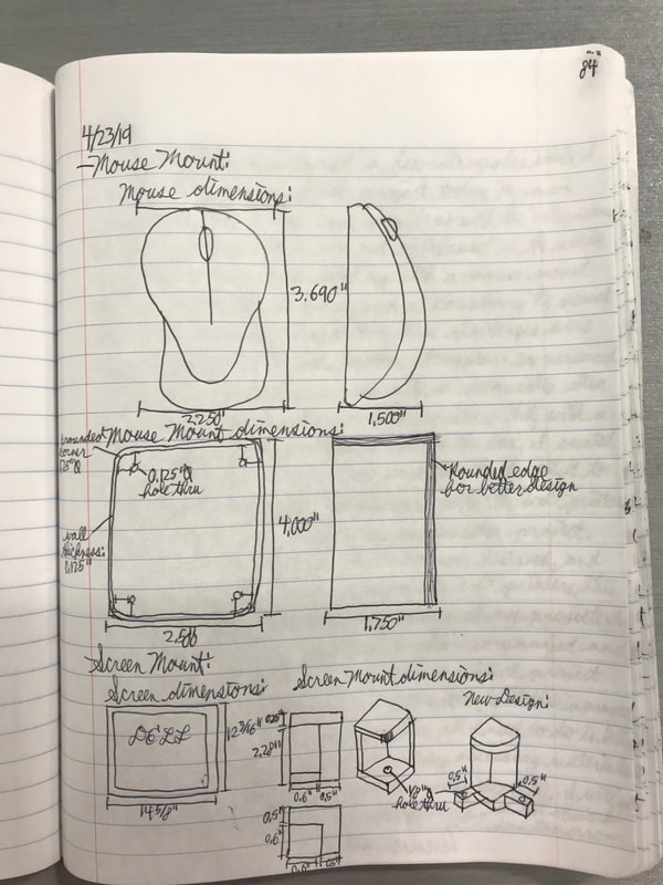
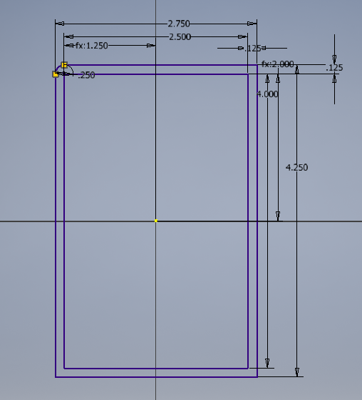
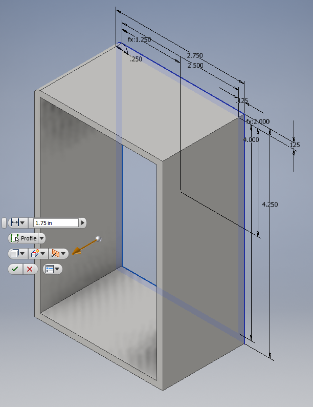
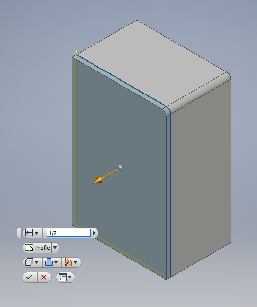
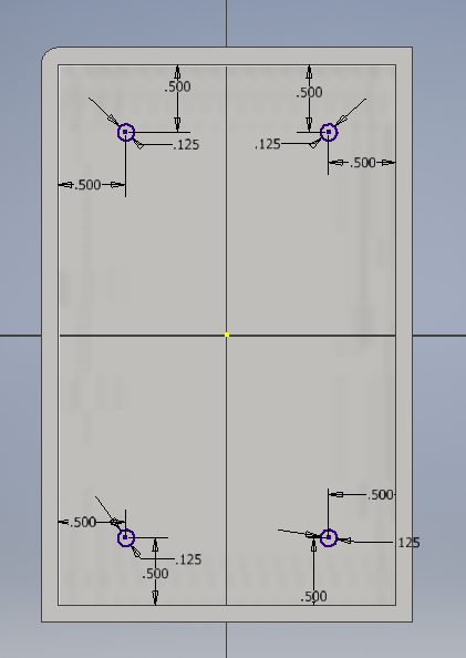
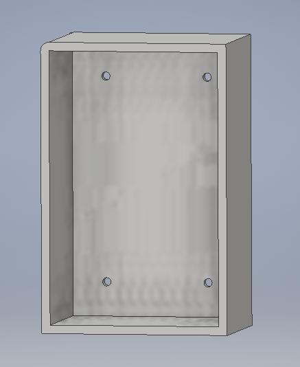
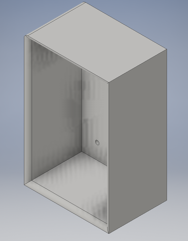
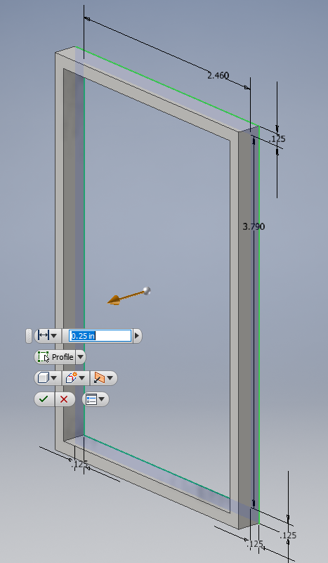
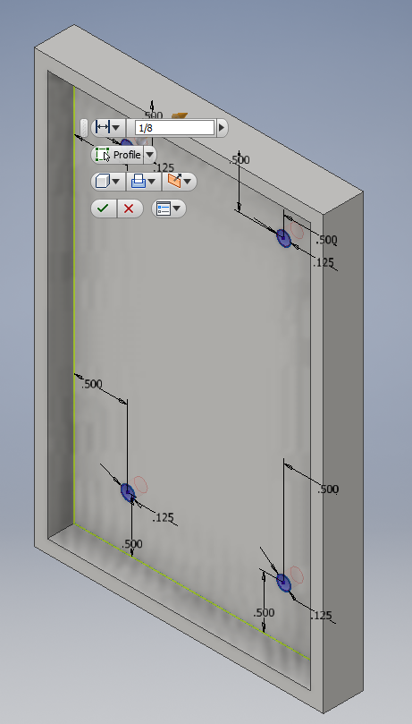
I decided that I should have a mount to store my mouse when the case was in storage mode, so I designed it in Inventor, using the dimensions above. I then extruded it to the right height, and extruded the bottom the minimum amount (1/8 inch) for the 3-D printer. Next, I placed the holes that are fit for a 1/8 in. diameter screw. Finally, I rounded the top corners for a more pleasing design, and exported the file to be printed.
|

|
|
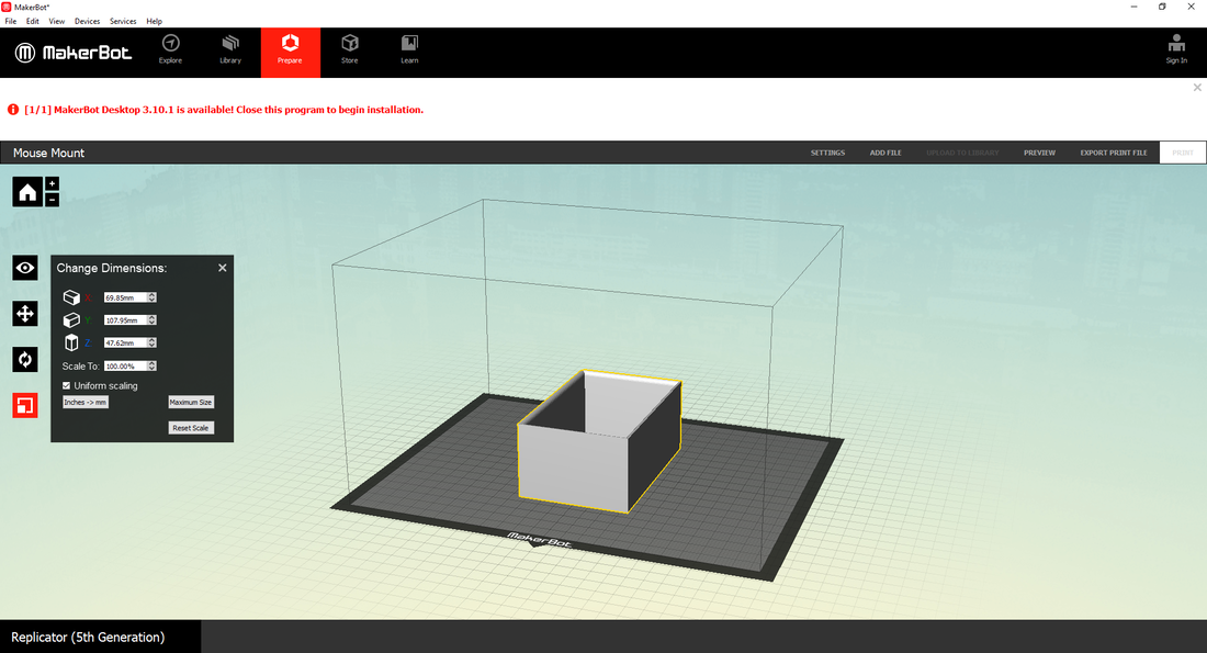
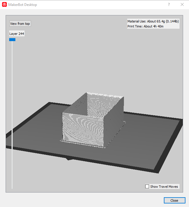
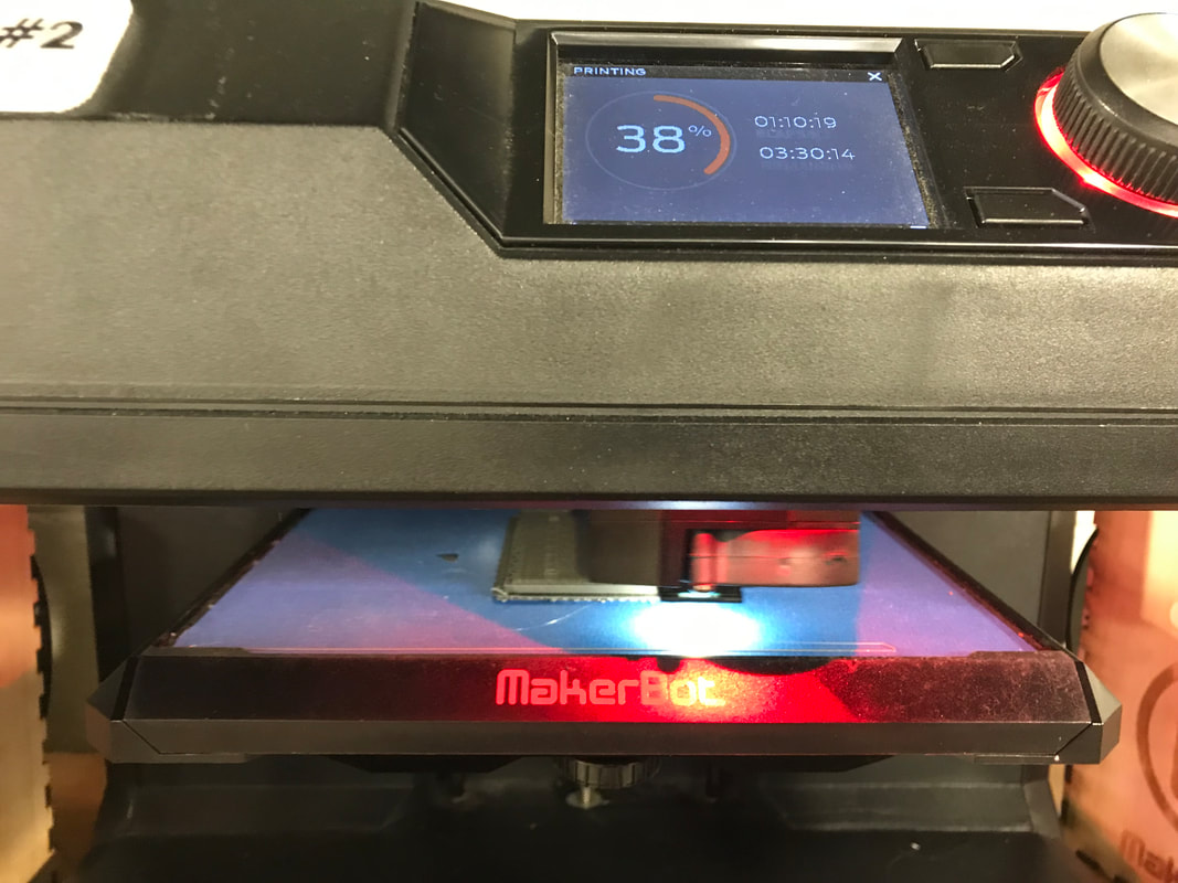
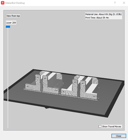
In the MakerBot program, I set up the print like any other, and made sure that the setting were correct, so I wouldn't have to redo it. After the settings were saved, I exported the file to my flash drive, and previewed the print, which is shown on the right. It was small and thin, so it only took about 4.5 hours.
|
|
|
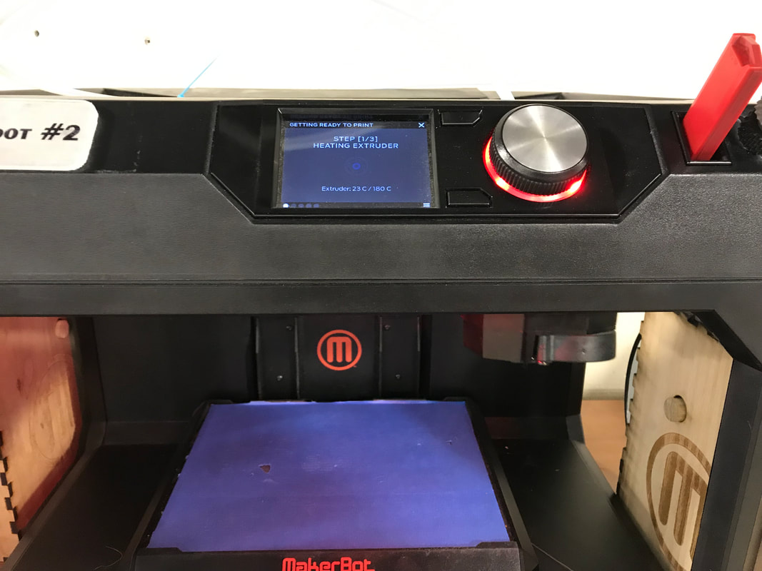
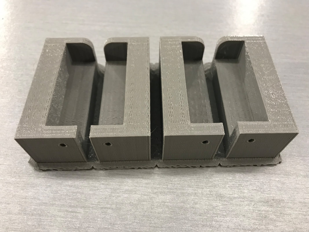
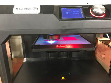
I uploaded the file to a 3-D printer, and started the print. My only problem with this part was that the printer must have run out of filament. Someone reloaded a gray filament, but it didn't quite match the silver that I started with. I decided to go with it, as it isn't really noticeable, and really was more of a functional piece than a decoration, so I left it as it was.
Mounting the Screen
|
|
|
|
|
|
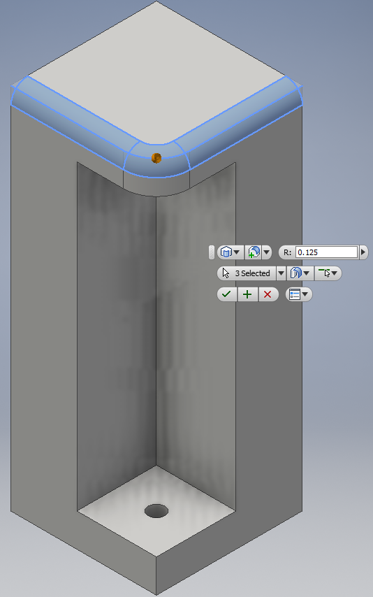
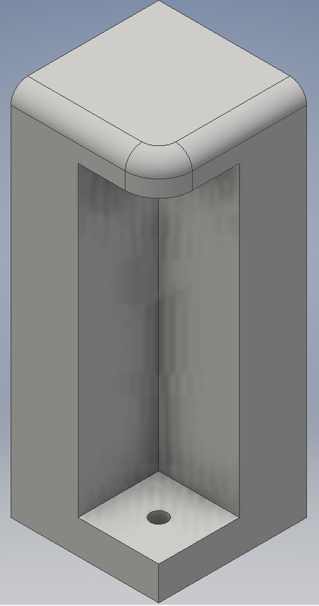
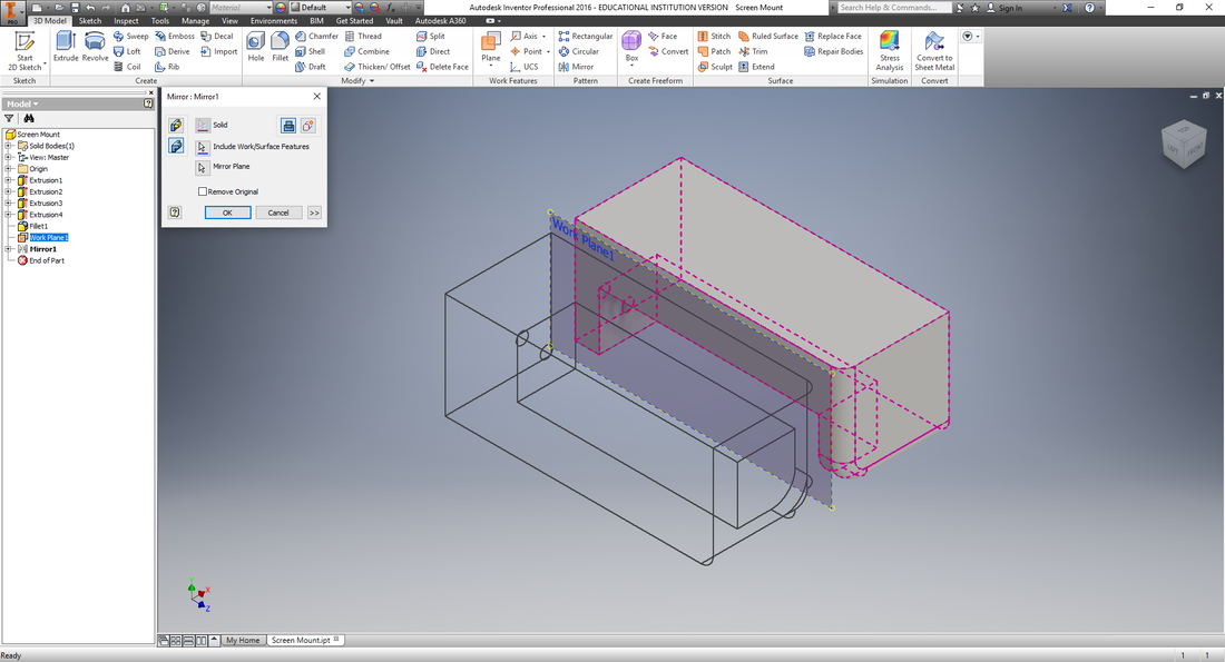
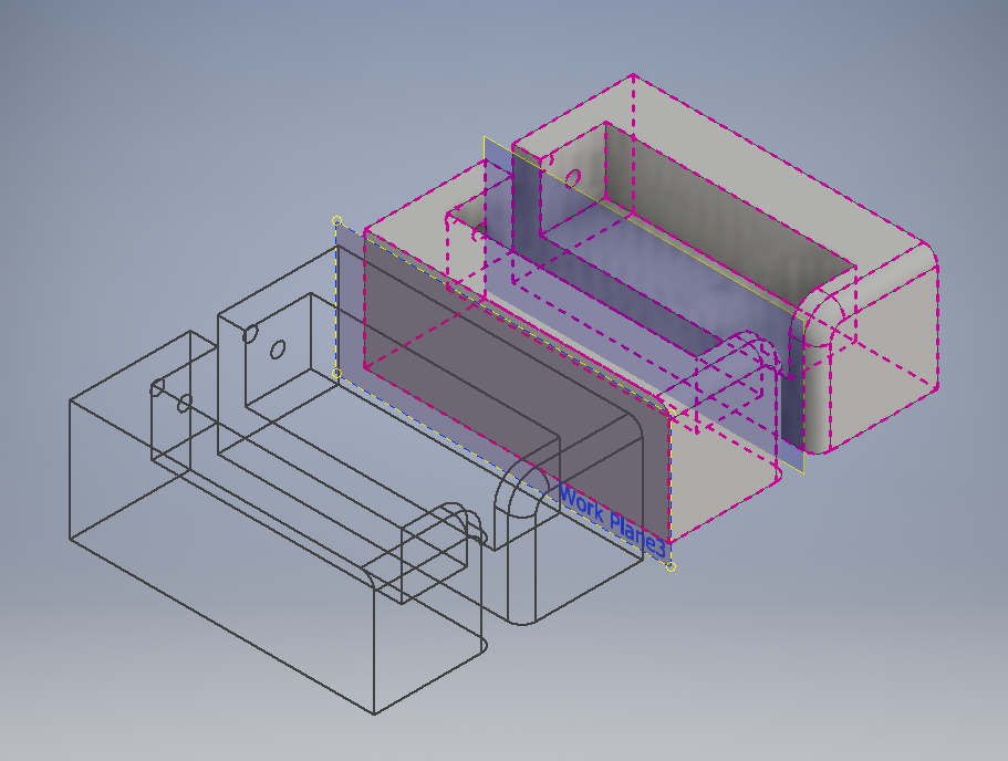
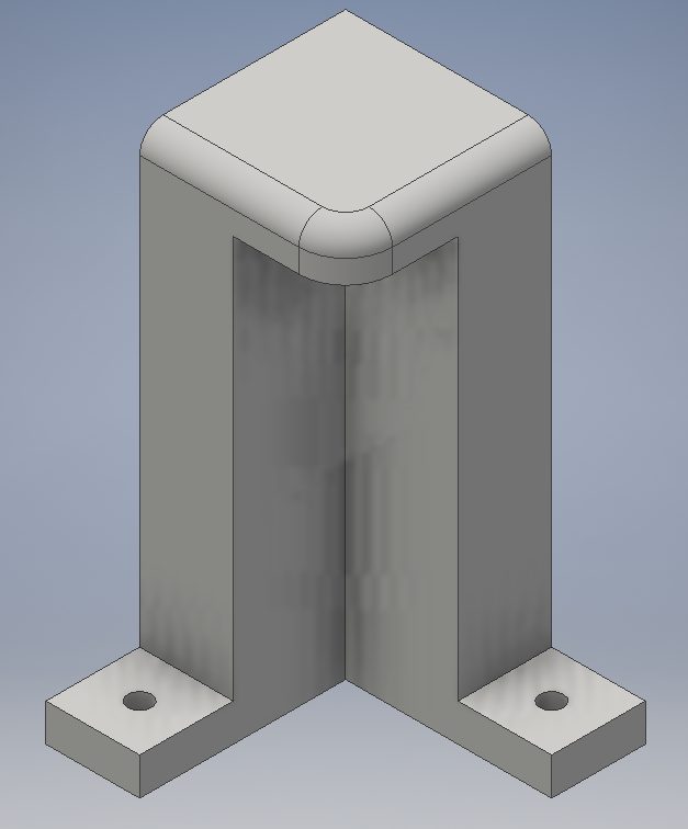
Using the measurements that I took of the box halves, as well as the monitor that I planned on using, I designed the screen mount. I created a corner piece that was 0.5 inches thick on either outcrop. I then extruded it to the height of the monitor, then added a cap piece that covers are much of the corner of the monitor as possible for strength without covering the screen itself. I then added a hole for the correct size screw, and finally rounded the top edge for aesthetics.
|
|
|

|
|
|
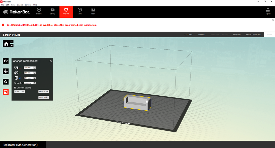
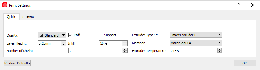
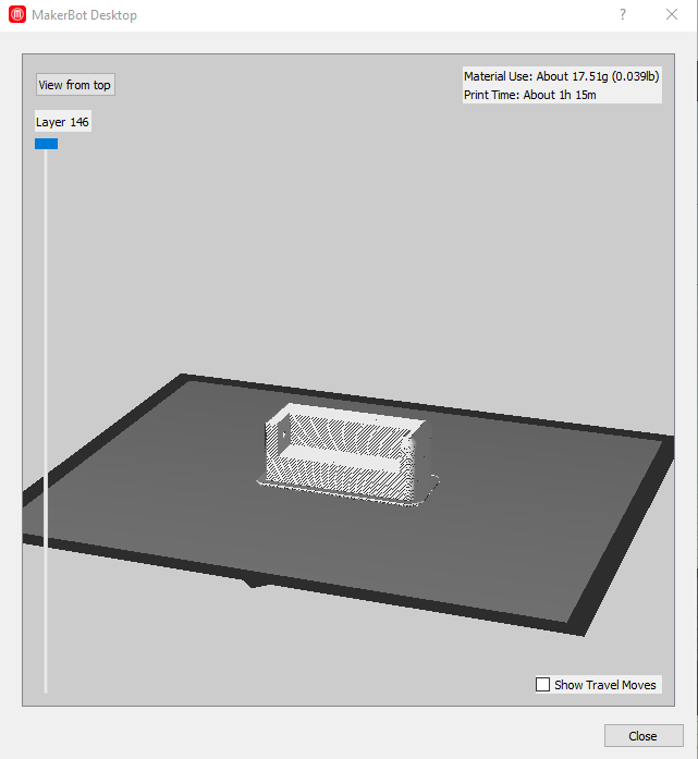
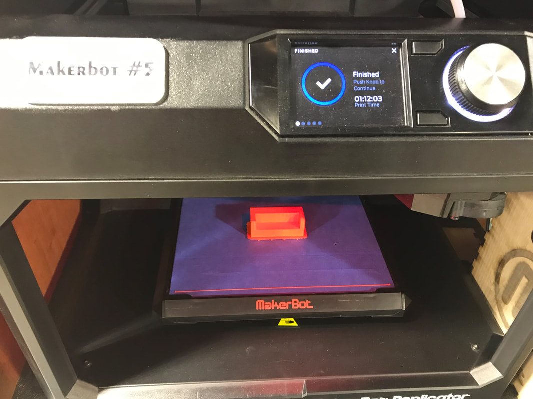
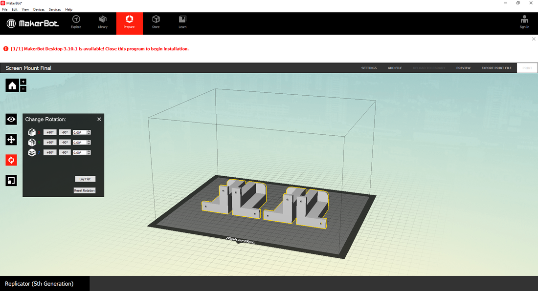
Once the screen mount was designed, I exported it to the MakerBot program, and performed the same setting checks as I did for the mouse mount. I then previewed the file, then loaded it onto a MakerBot. It only took an hour and 15 minutes, and I only chose it to be orange as it was only a prototype, and I only needed to test its design rather than its color.
|
|
|
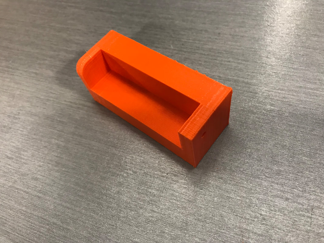
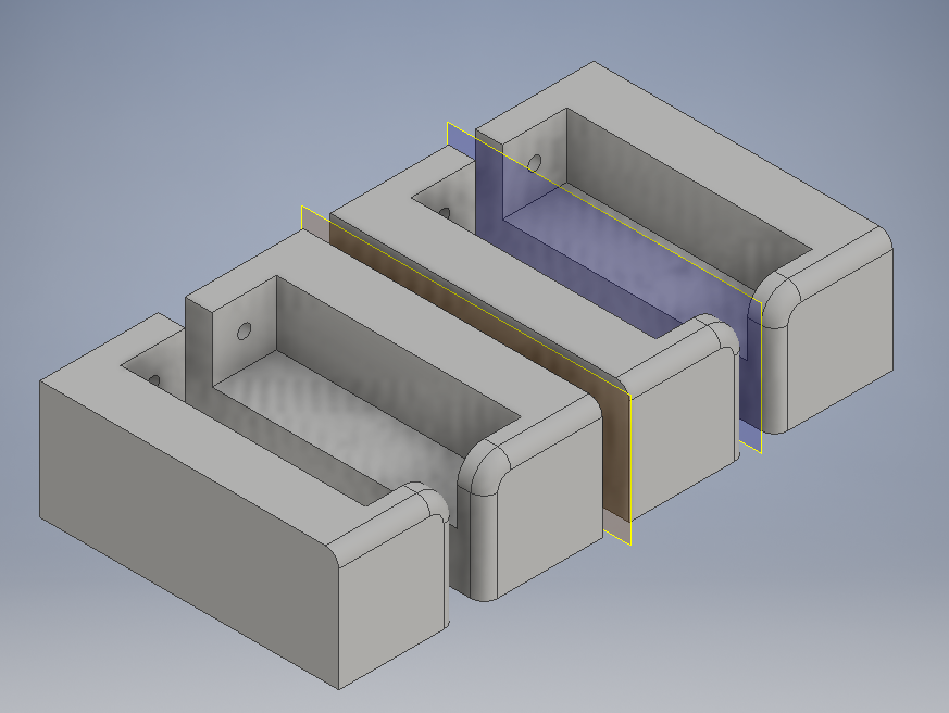
I found the prototype sufficient for my project after testing it with the monitor, so I went back into Inventor. I used planes and the mirror function to duplicate the part so there would be four of them. I left only a little space between them so they would print separately, but not waste filament building more rafting than necessary.
Righting a Wrong
|
|
|
It was only after I printed the four screen mounts that I realized my mistake. The holes were blocked by the monitor cover on the top of the mount. I had no way to screw them on square. In addition, I would have to put the screen in after I put two of them in, so I couldn't even access the other two screw holes. Consequently, I went back to the drawing board. I had to think of a way to make the screen mount holes accessible to all sides.
Perfecting the Screen Mount
|
|
|
|
|
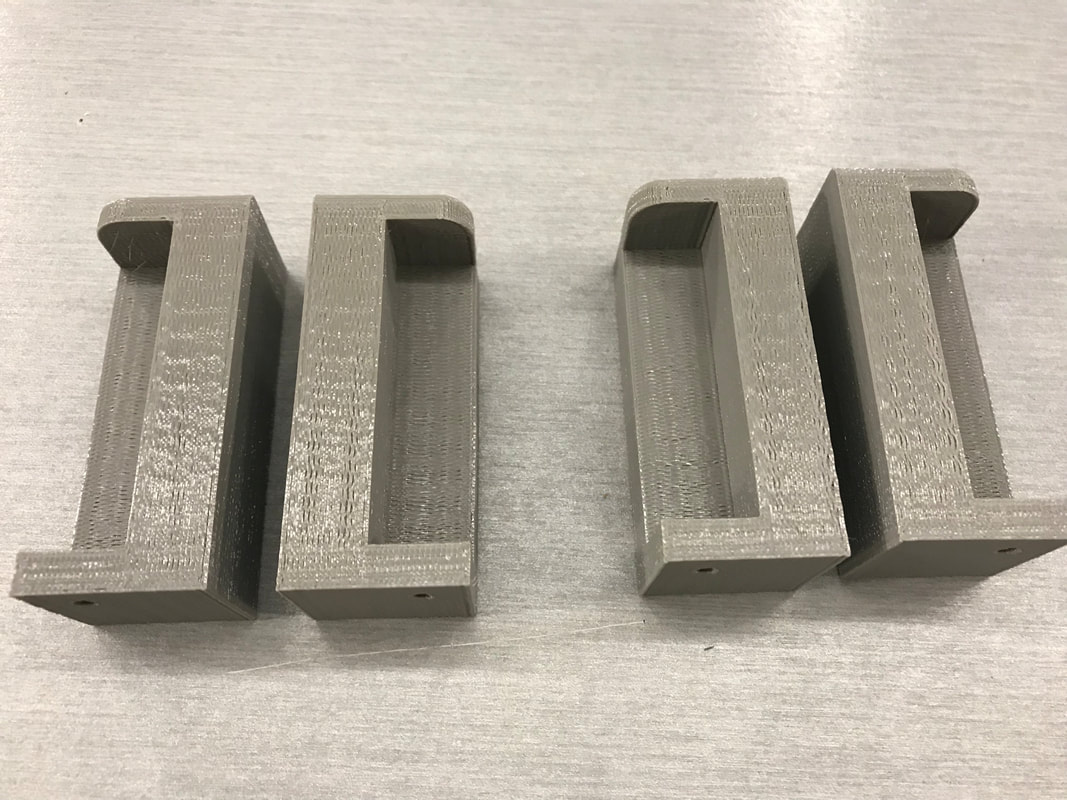
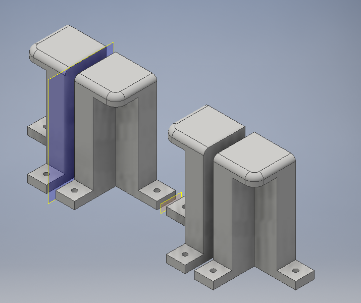
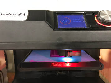
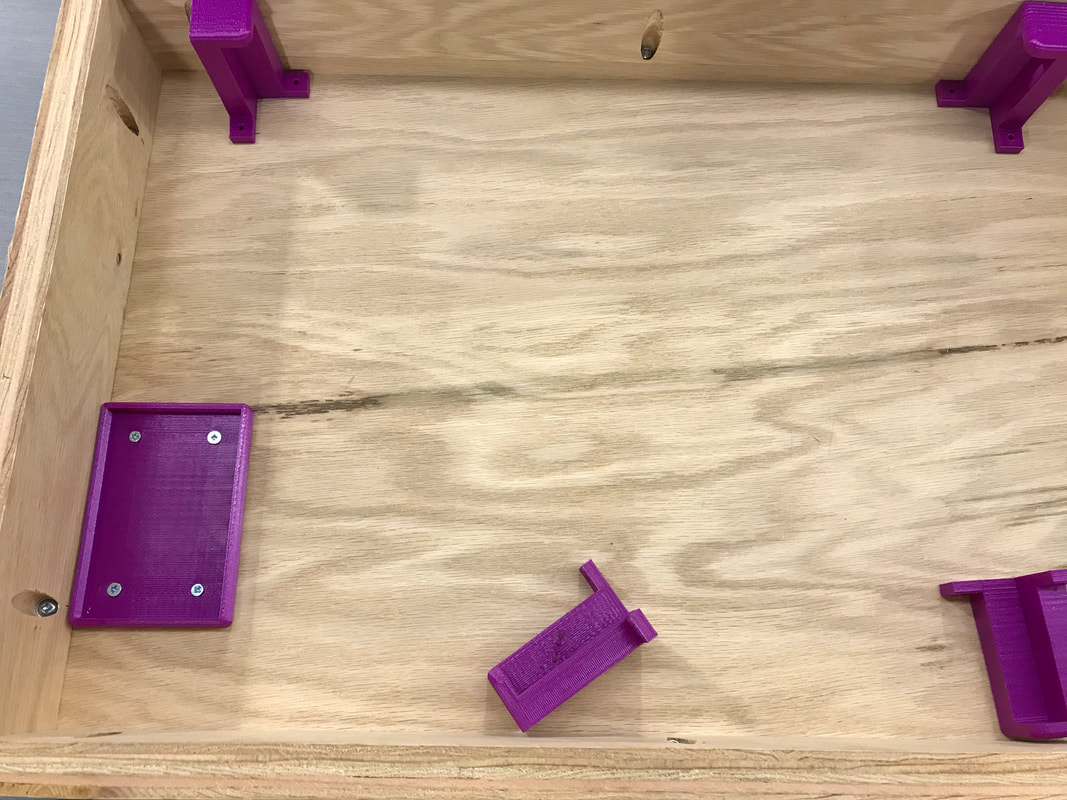
Consequently, I went back to the drawing board. I had to think of a way to make the screen mount holes accessible to all sides. Finally, I got it. I thought of a way to have the holes accessible when I assembled the monitor into the lid. I would have a square with 0.5 inch sides extrude from each of the extrusions of the original design. That way, the 0.5 inch gap that I left on both sides of the monitor will allow me to attach the monitor to the briefcase lid much easier. I made my adjustments, re-made the MakerBot file, and printed it out. I used raspberry colored filament for this because I thought it would complement the Raspberry Pi well. This version worked instantly better, and performed perfectly with the monitor.
Mounting the Processor
|
|
|
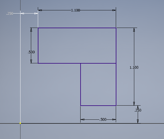
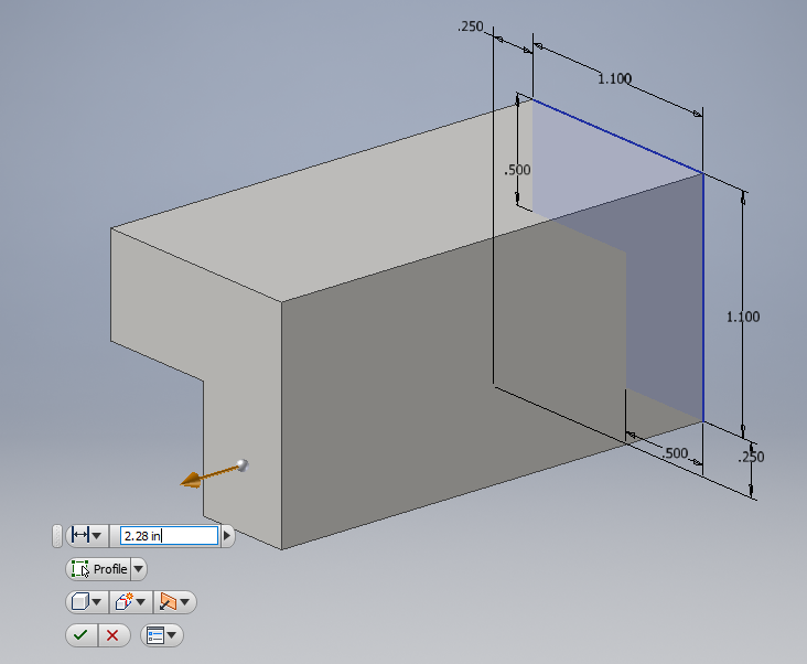
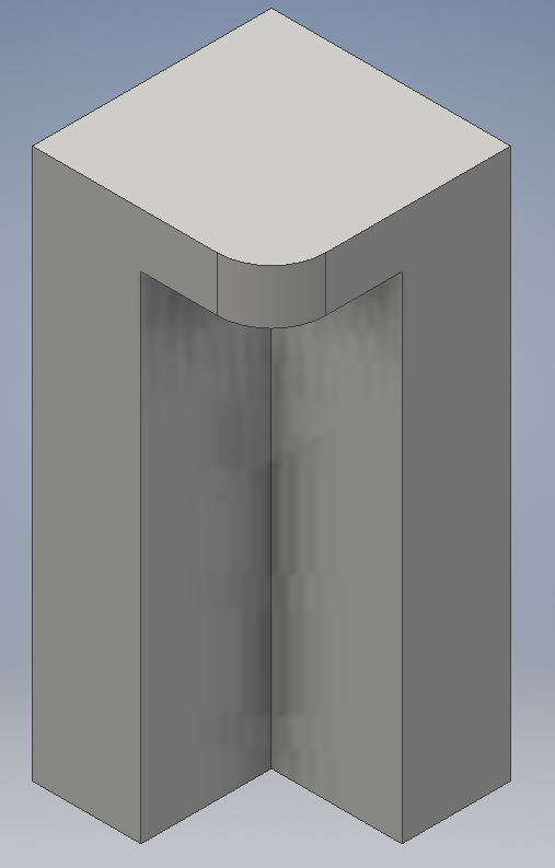
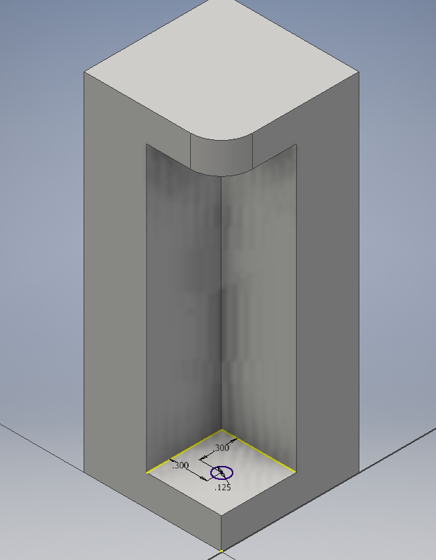
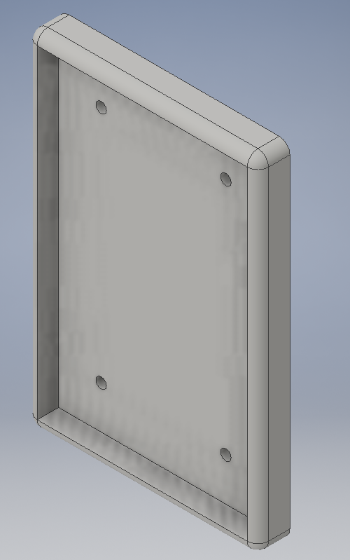
Next, I realized that I needed a way to mount my Raspberry Pi into the briefcase lid. My original plan was to build a drawer that would pull out and stand up, allowing cables to be plugged unto it. I then figured out it would be easier to have a mount in the lid that would hold it. Then, I designed it in Inventor, using specific dial caliper measurements that I took of the Pi, just large enough to encompass it, but tight enough to hold it in.
|

|
|
|
|
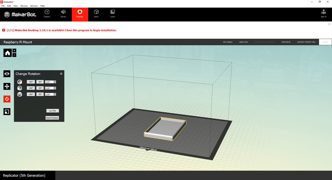
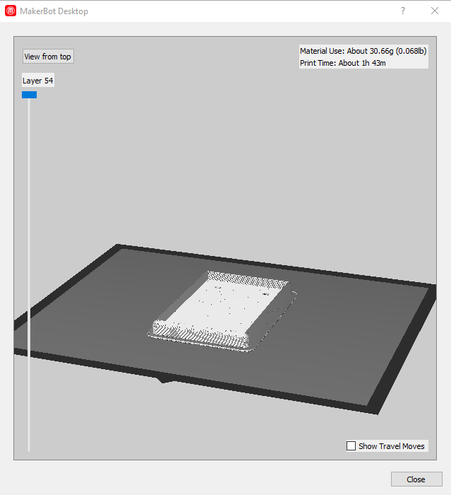
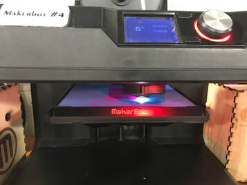
Using the same procedure as the other 3-D printed part, I exported the file to MakerBot, double-checked the settings, and previewed it. I decided to make it out of a raspberry filament as well to match the Raspberry Pi theme. I ran out of filament on this project as well, so it was restarted for a better result.
First Assembly
|
|
|
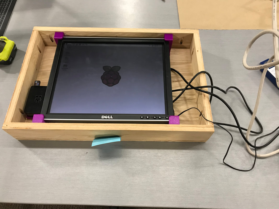
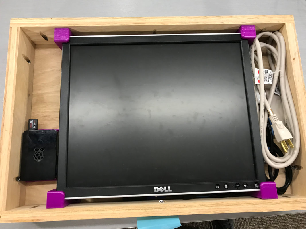
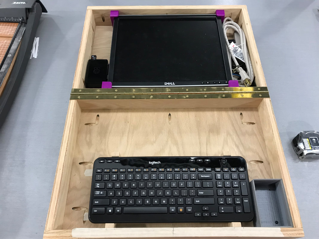
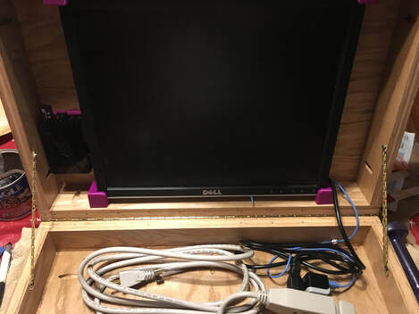
I started the first assembly by screwing everything into the lid of the briefcase. With the help of Mr. Willauer, I placed the Raspberry Pi mount where I wanted, then we put the Pi into the mount with the cords plugged in. Next, keeping the cords where we wanted them, I screwed the left two screen mounts down, and inserted the screen. I then carefully placed and screwed down the last two mounts on the right side of the monitor. We then made sure that all electrical components worked. I connected the Pi to the monitor, and plugged all power cords into the power strip that I picked up from Ace Hardware. Everything worked perfectly, as it did the first time I assembled the electronics.
Mounting the Keyboard
|
|
|
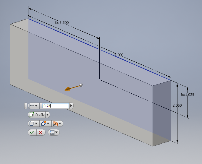
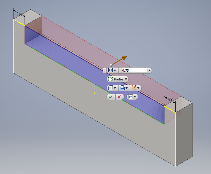
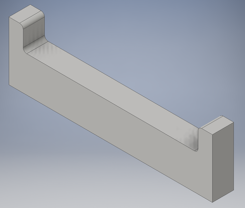
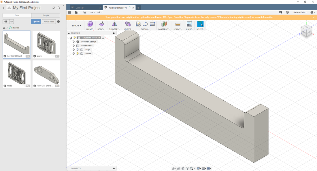
I then moved onto the bottom half of the briefcase. The only thing that I needed was to create the keyboard mount. To gain my third machine for the project, I decided to make it on the CNC Router. I first designed it to match the keyboard that I bought from Best Buy. Again, I used the capabilities of Inventor to create my mount, as illustrated above.
|
|
|
|
|
|
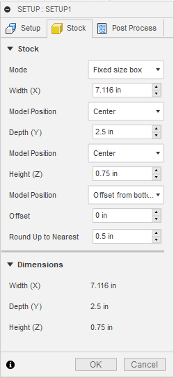
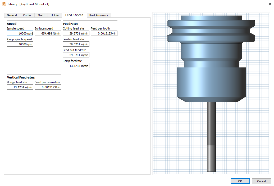
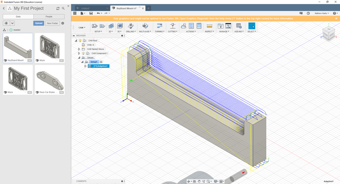
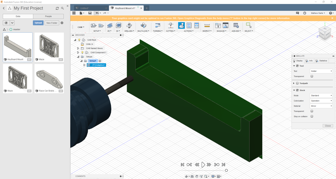
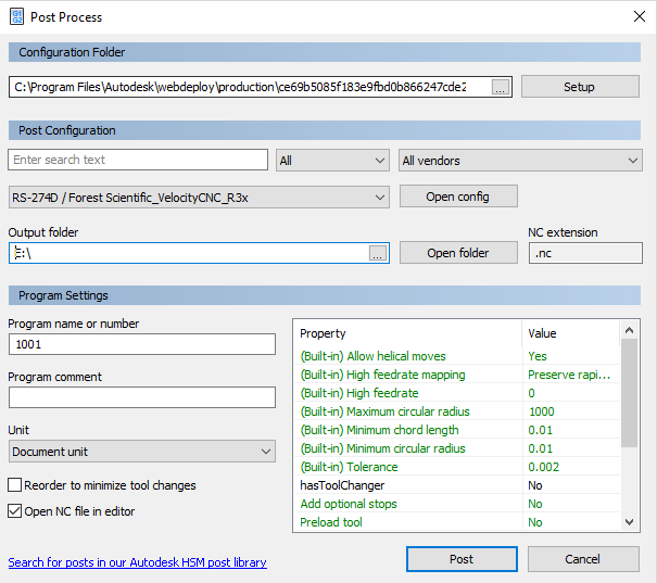
Following the Fusion 360 instructions from the handout, I imported my file into Fusion 360. I set dimensions for the stock surrounding my part file, and set up the drill bit size and shape. Then, I set up my tool path that I was going to use, and previewed how the part was going to be cut out. Finally, I posted the G-Code to my flash-drive, and I took it to the Router.
|
|
|
|
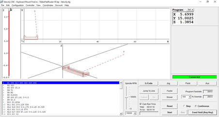
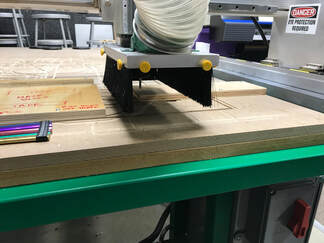
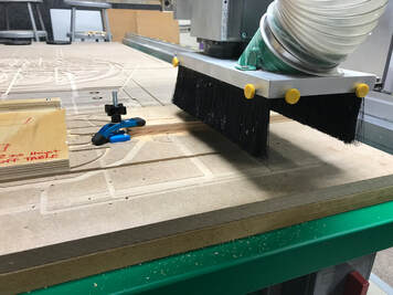
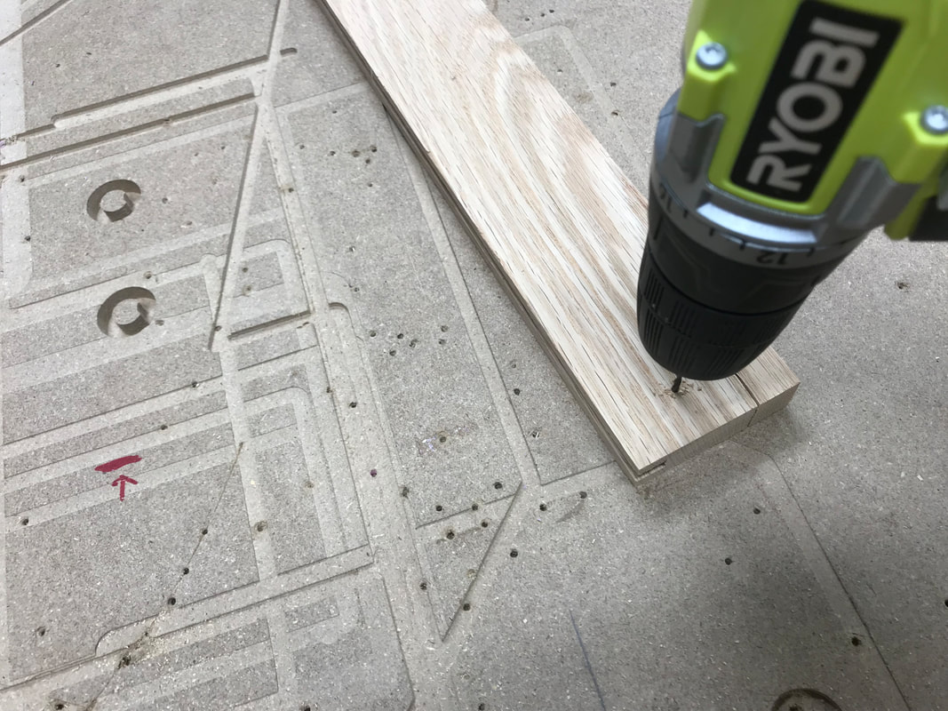
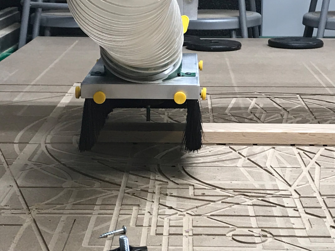
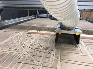
Once on the router, I screwed down the piece of oak plywood that I planned on using for the mount, and I loaded the G-Code. I then set and zeroed the x and y-coordinates for the router, and I used the sensor to set the z coordinate. At last, I was able to run the program. I stopped the router once it was almost done so that I could attach a clamp to keep the piece in place. After it finished, the first thing that I noticed was that it stripped out some of the inner layers of the piece as it cut it, which I should have expected from plywood.
|
|
|
|
|
|
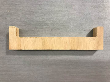
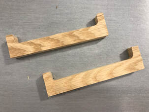
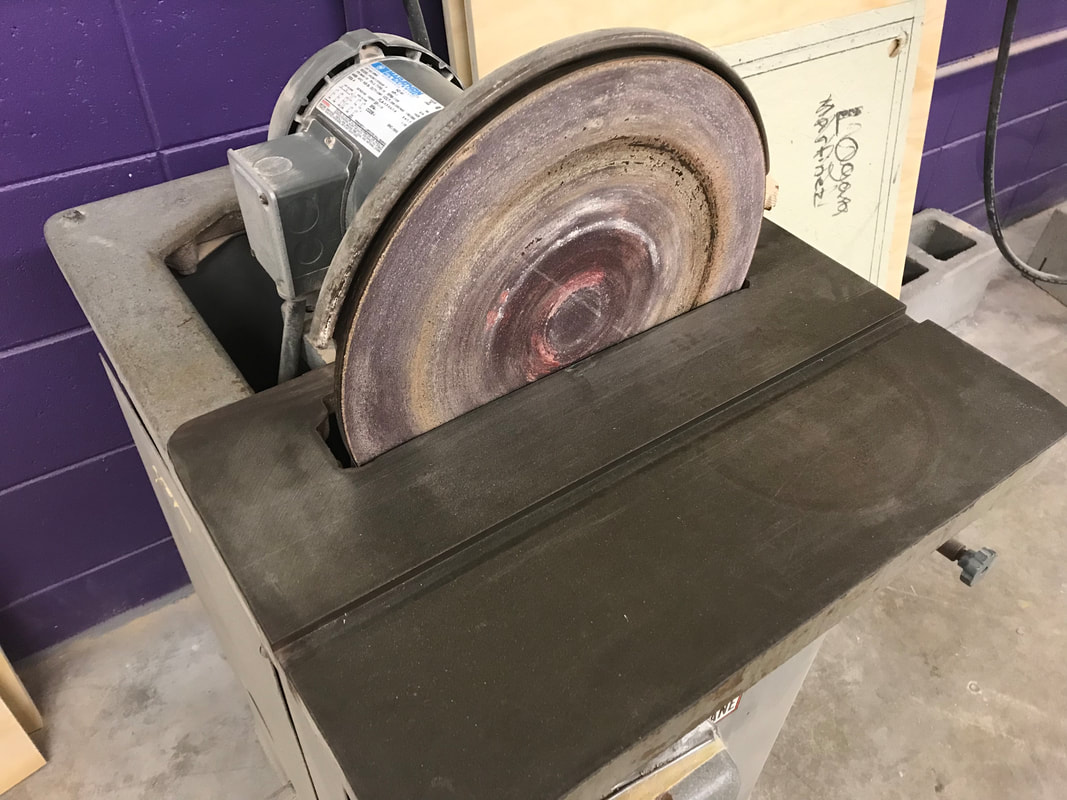
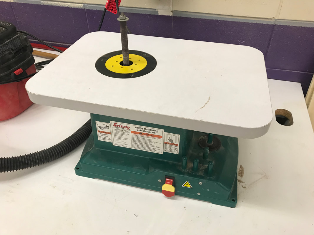
I decided to use solid oak wood for the actual mounts. I had to move the piece towards the middle of the router bed to keep the edges true and square. I then cut out the program twice, and got my two mounts. I was happy with the way both mounts turned out. With Mrs. Proctor's help, I used the orbit and disk sander to smooth the edges down. I was then ready to attach them to the briefcase bottom.
|
|
|
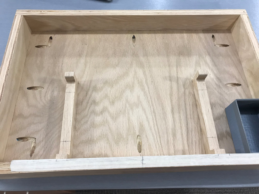
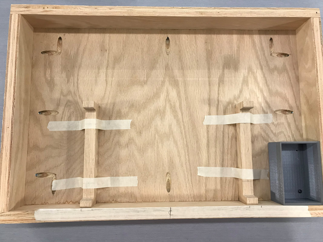
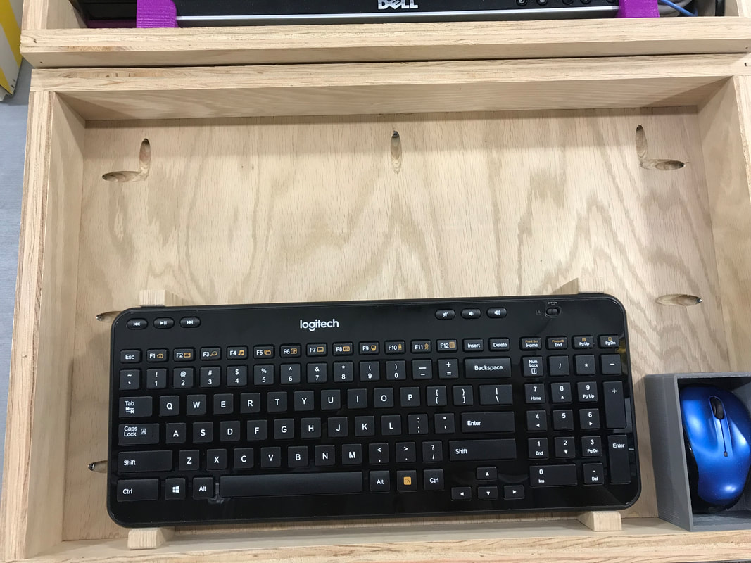
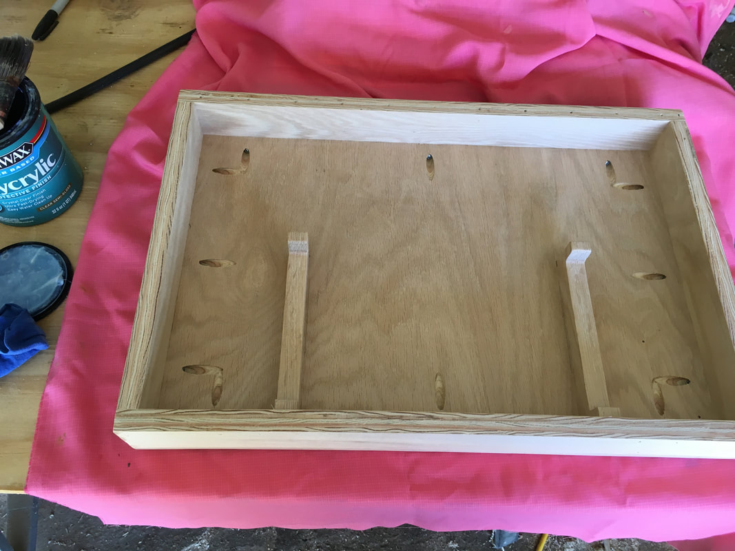
With some guidance from Mr. Willauer, I attached the keyboard mounts using wood glue. I first measured out exactly where I wanted the mounts to be in the bottom, then I applied wood glue to the underside of the mounts, and aligned them with my measurements. To hold them in place while the glue was drying, I taped them down with masking tape. The glued dried perfectly, and the mounts perfectly fit the keyboard when I tested it later.
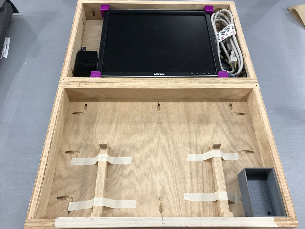
Hinging - Take 1
|
|
|
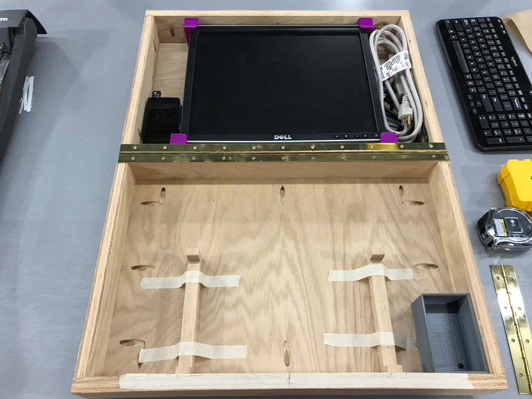
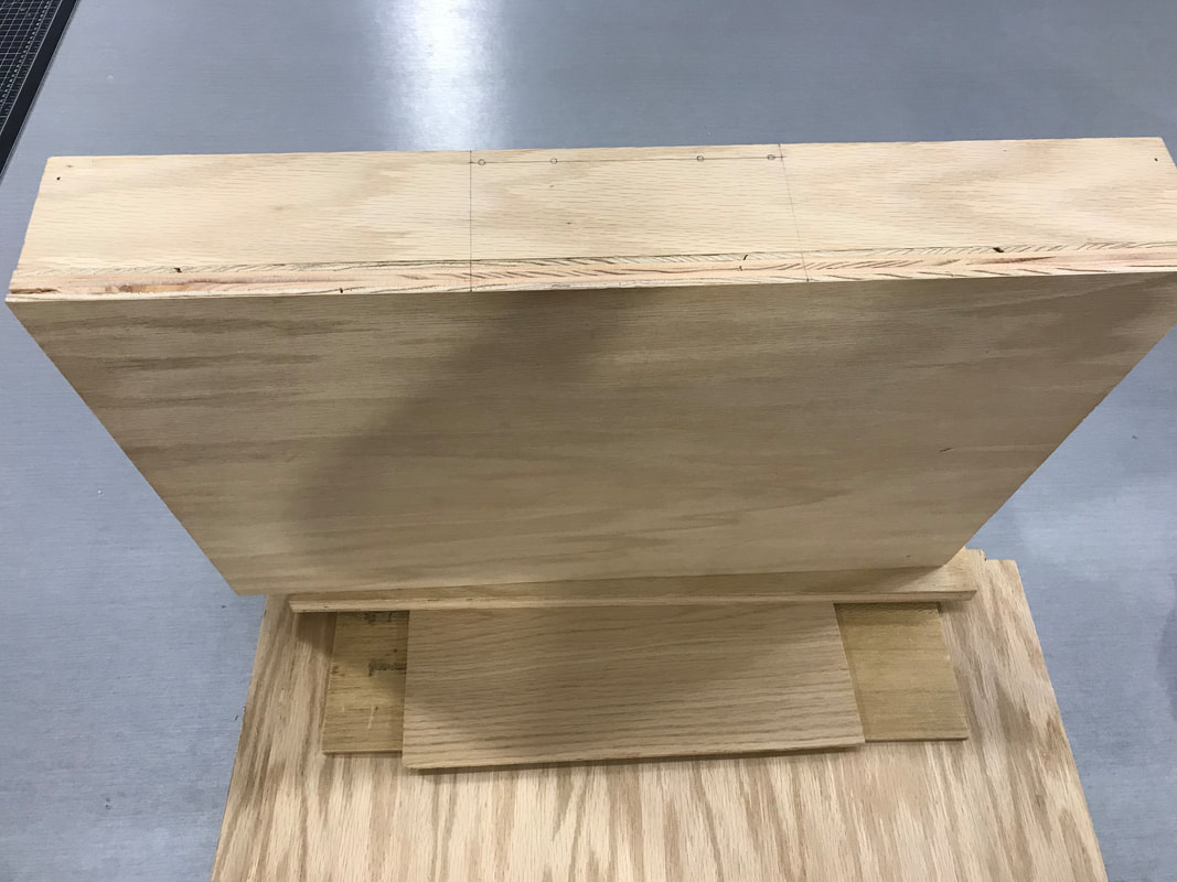
Once the two halves were finished, I figured the next logical step would be to attach them together. The only challenge I had with the two halves was that the bottom half was 0.75 inches shorter than the top half, so I had to find a 0.75 inch thick piece of plywood to stack under it. I then folded an index card in half, ripped it down its length, and put each half between both halves so that the hinge would have a small gap to work with. With the hinge in place, I circled the holes in pencil using the holes on the hinge as a guide. and pre-drilled them, as the brass screws were a softer metal. I then put the hinge on without too much trouble, and I suddenly had a whole box.
Exterior Components
|
|
|
|
|
|
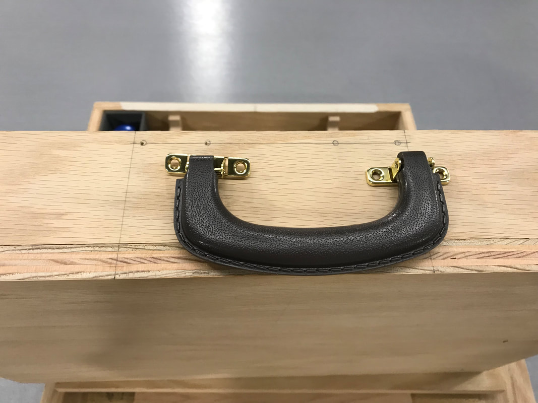
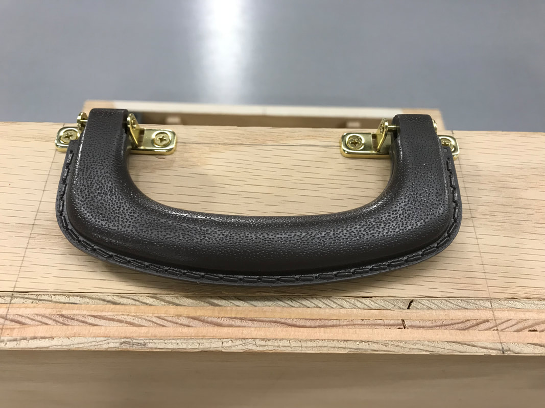
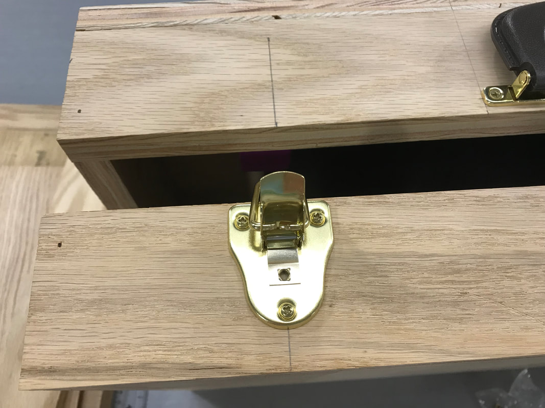
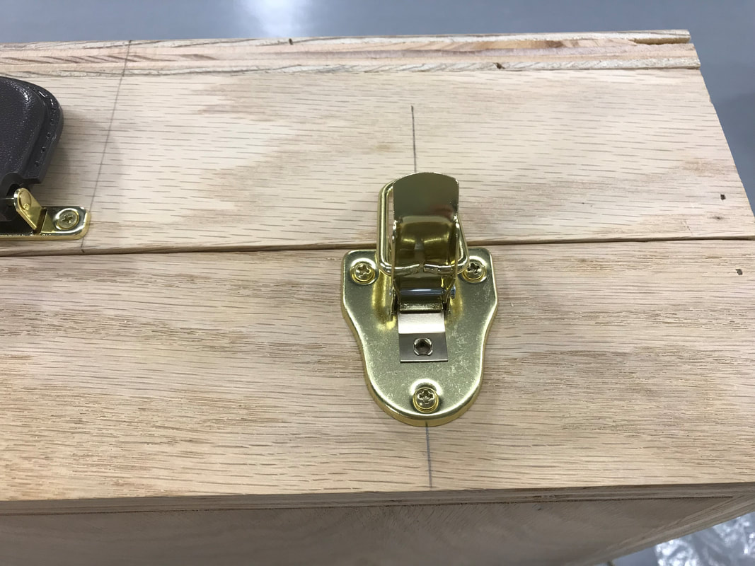
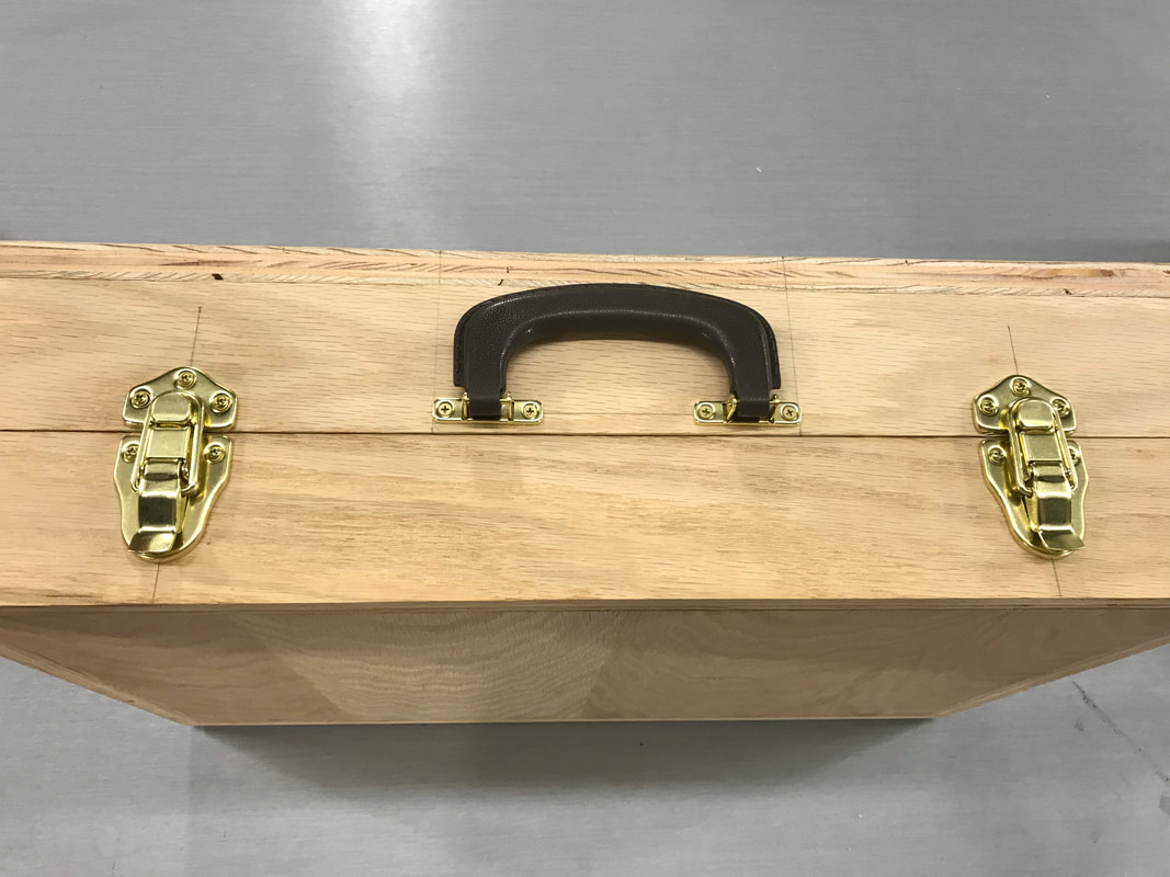
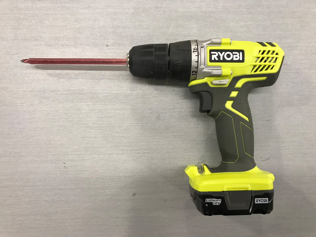
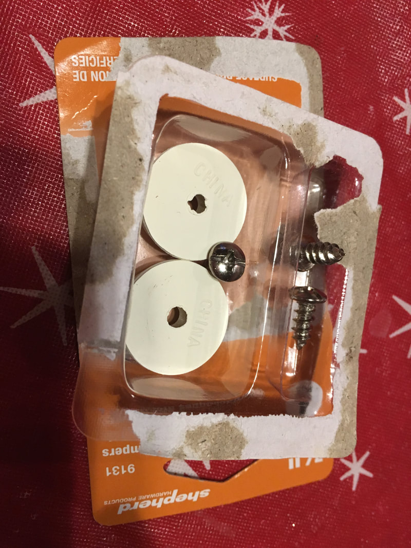
When I got home on Monday, May 13th, I was very happy to see that my ordered parts came in the mail in one business day rather than 10! I was then able to shift my schedule up a day and continue with the first assembly. I first did the handle, since it was closer to the inside of the briefcase. I first did precise measurements to determine the exact center of the box. Then, I lined the handle screw holes with the lines that I drew, and outlined the holes. Next came the pre-drilling, and I was finally ready to put the handle on. Once it was secured, I started on the latches. They were a bit easier, as the measurements were rounded to the nearest inch and were easier to make square. I did the same things with them as the handle; first the tracing, then the pre-drilling, and finally the screwing. Once it was done, I tested how it worked. The handle held up to the weight of the briefcase, and the latches held it shut! The only problem with the latches was that the two halves didn't match up perfectly, so the latch parts weren't perfectly level.
Undoing 15 Weeks of Work in 15 Minutes
Once I finished assembling the briefcase for the first time, I had to disassemble it after I showed Mr. Willauer that those were the parts that I were going to use. I needed to do this for several reasons; so that I could sand all of the wooden surfaces, and to paint and seal them. It only took 15 minutes to disassemble all of the hard work that I put into the project in 15 weeks!
Laser Engraving
|
|
|
|
|
|
|
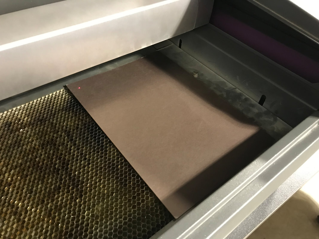
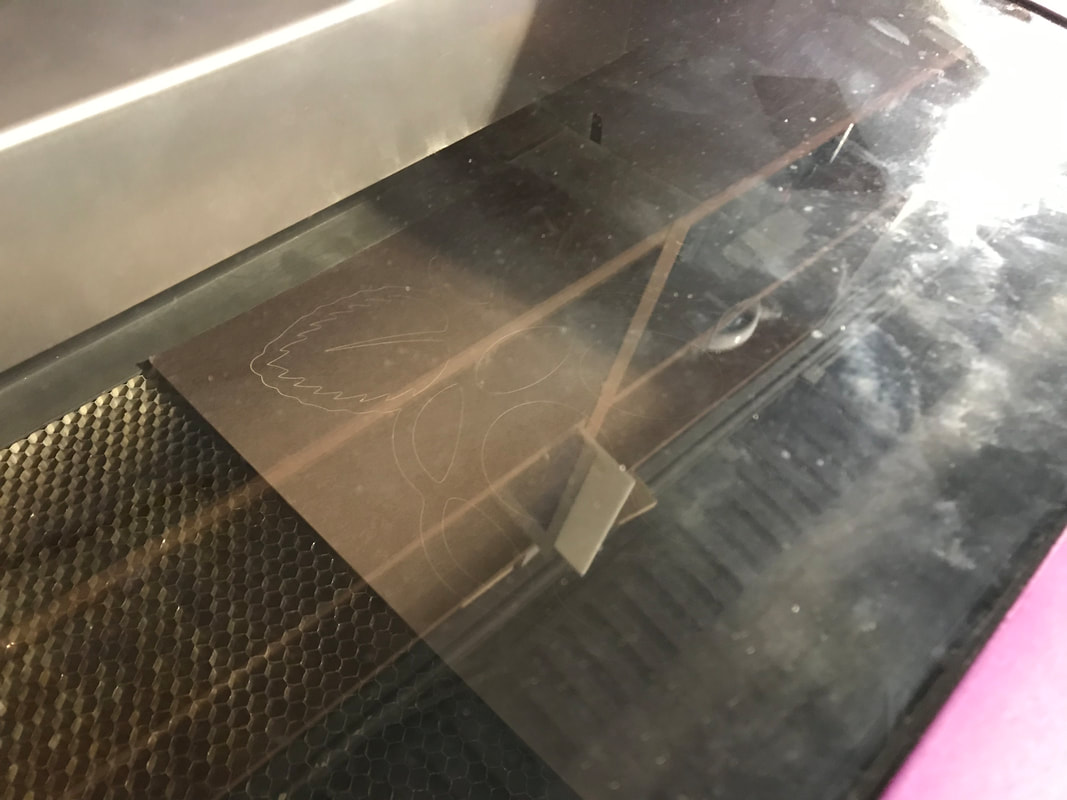
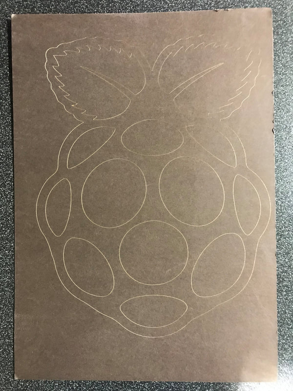
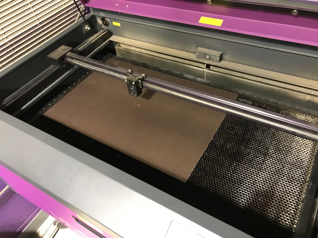
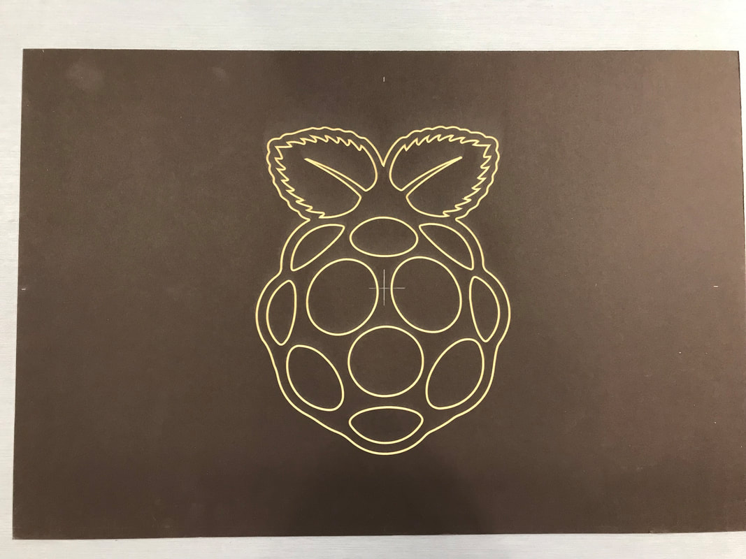
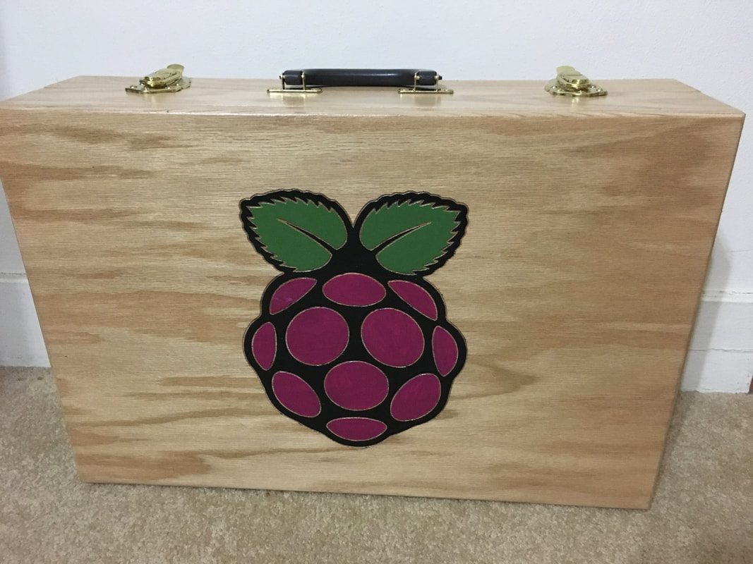
I was then able to laser engrave the briefcase lid. I decided that the Raspberry Pi logo would be appropriate, so I found a design online. I used Illutrator to convert the file to a usable path for the laser. Then, I exported the file to my flash drive, and opened the print menu. I chose the correct material, imputed the thickness, and double-checked the settings. Then, I moved the logo to be cut out on the smallest piece of mat board possible. I later moved it to the would be center of my briefcase lid to test its location.
|
|
|
|
|
|
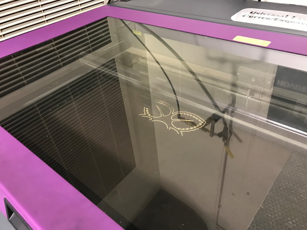
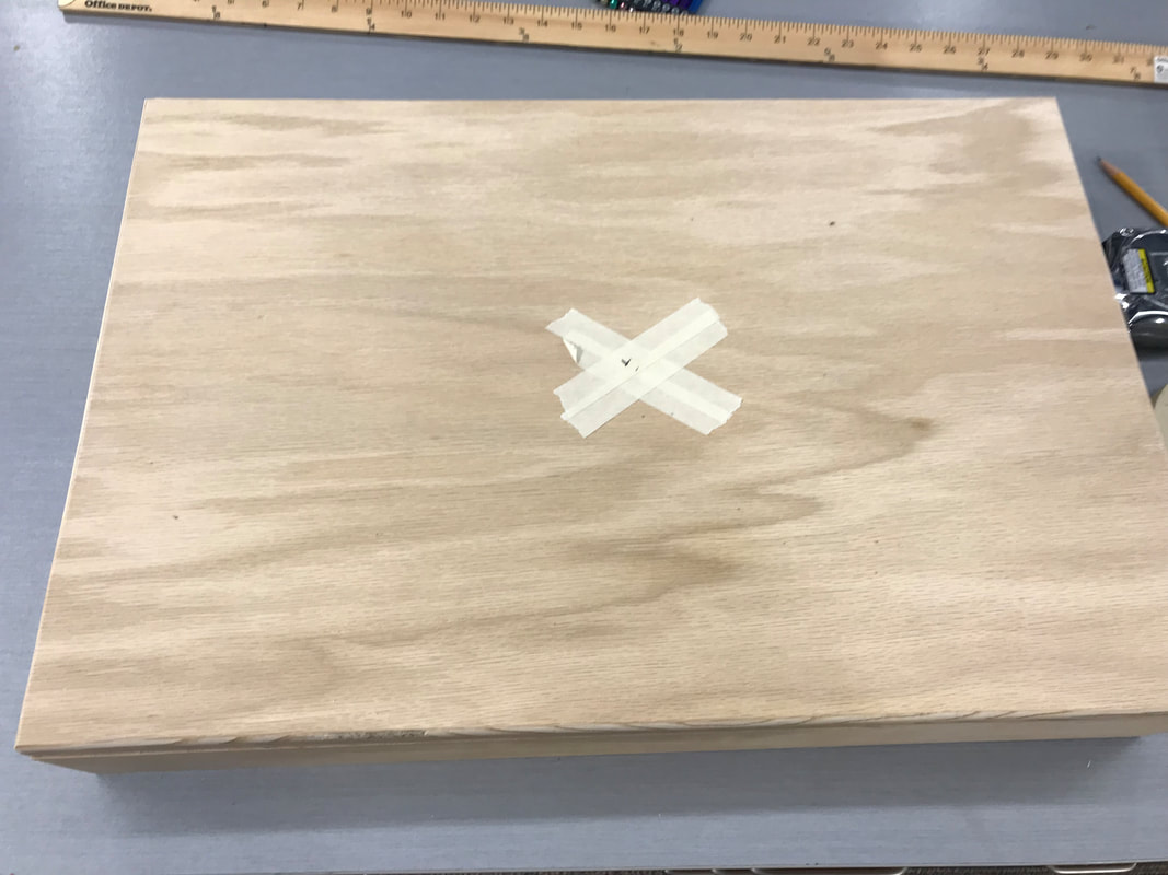
The top row of photos is the first engraving, where I tested solely the engraving itself, rather than its sizing. The next row of photos shows a test involving the location of the engraving as well as a change in the stroke weight. It turned out perfectly, so those changes were what I planned to use for my project. This was done a few weeks before the actual engraving, since I had the time.
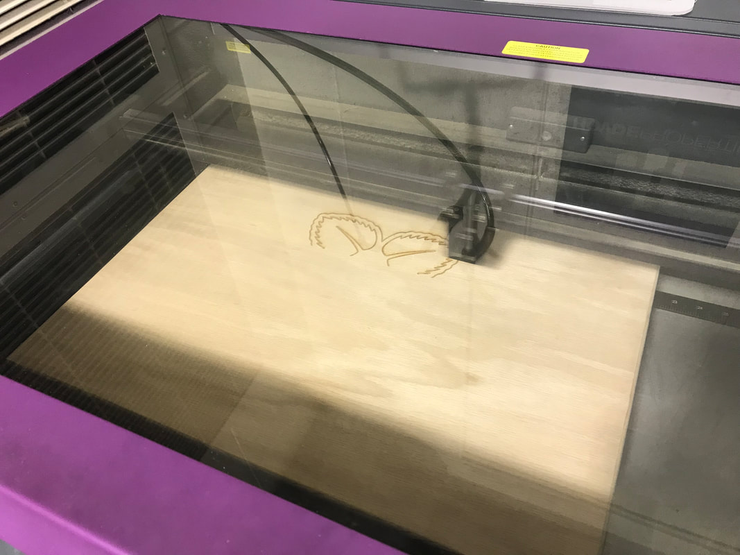
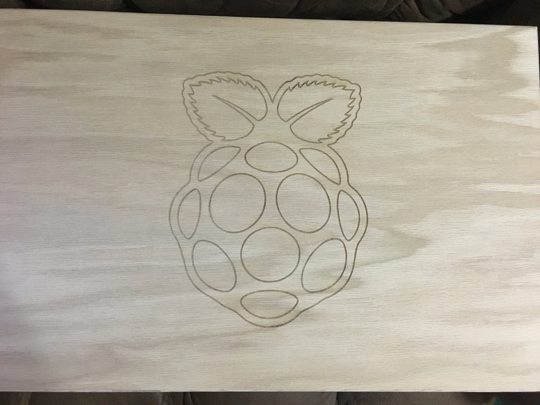
Final Laser Engraving
|
|
|
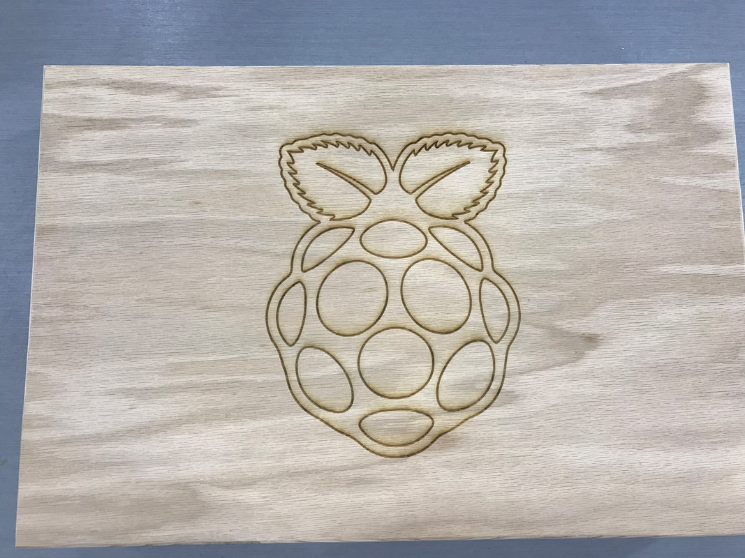
Once I had time, I used my perfected Illustrator file to engrave the lid of my briefcase. To make sure the engraving was perfect, I carefully measured from the opposite corners with a yardstick to center the laser perfectly. The file location was saved, so all I had to do was align the lid with the correct corner. Then, I started the program. It turned out exactly as I wanted, with the stroke weight thick enough for my future plans.
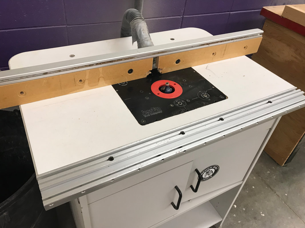
Routering and Sanding
|

|

|
The next step to my project was to round the edges just slightly to make the project more aesthetically pleasing. With Mr. Willauer's help, I used the table router in the woods lab to router the edges of the lid and the bottom. I then brought the halves home and sanded it with 80 grit sandpaper, and progressed to a higher grit as I sanded.
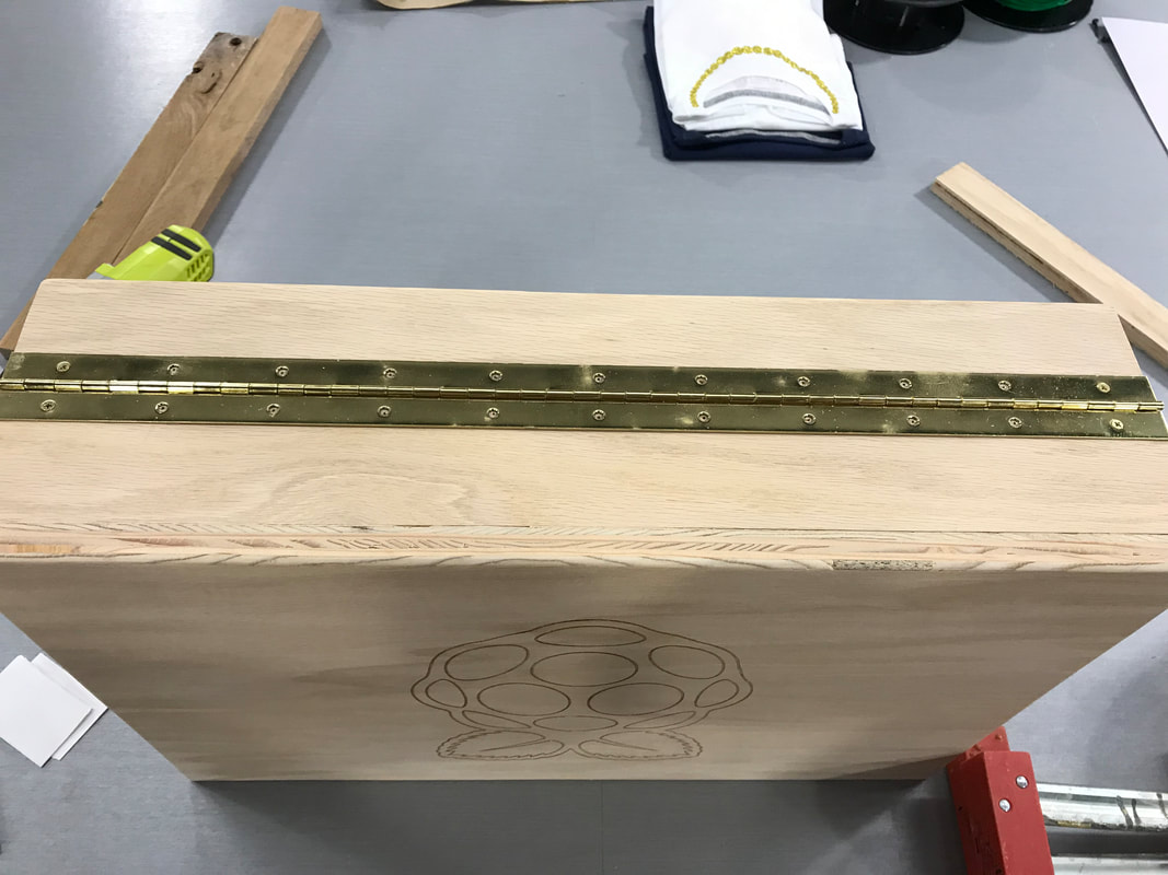
Hinging, Take 2
|
|
|
I realized after I put the hinge on that I really should have put it on the outside of the halves rather than in between them. This is because there was a small gap between the lid and bottom when it was closed. Consequently, I traced the screw holes, pre-drilled them, and attached the hinge. It looked better with the hinge on the outside, so I was happy with the result. The only problem that I had was that the wood clamps that I borrowed from Mr. Schumacher were a bit heavy to balance, but I managed in the end.
Painting
|
|
|
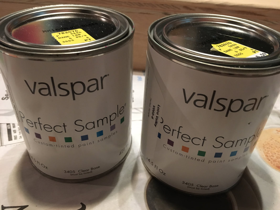
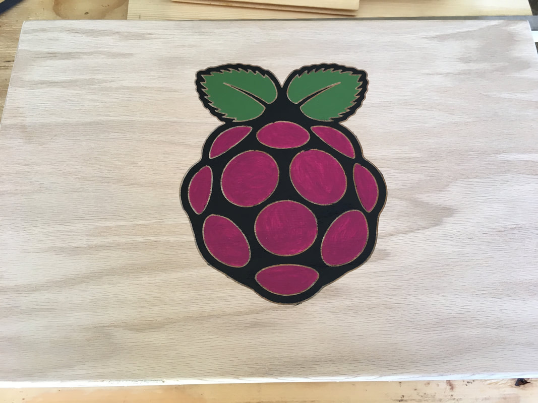
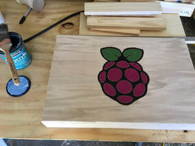
Next was the make-or-break part of the project: the painting of the logo. I got the paints I wanted from Dane Lumber, and I bought a raspberry color, as well as a plant green. I started with the leaves, since it was the lightest color. I then moved onto painting the raspberry color, and I painted both of these colors with two coats in order to cover up the brush strokes. Finally, I painted one coat of a matte black in the outline. I was ecstatic with the result, as I was very careful to not paint inside the engraving lines. This made the project look neater as a whole.
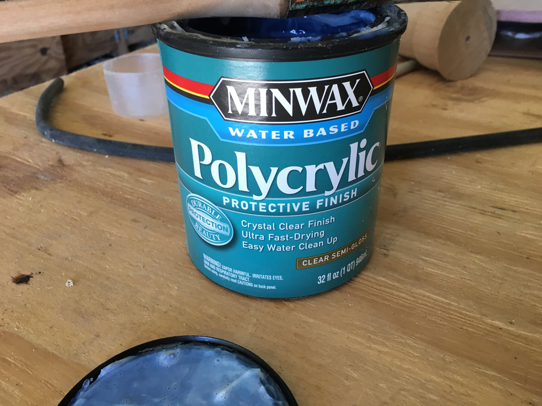
Sealing the Case
|
|
|
|
|
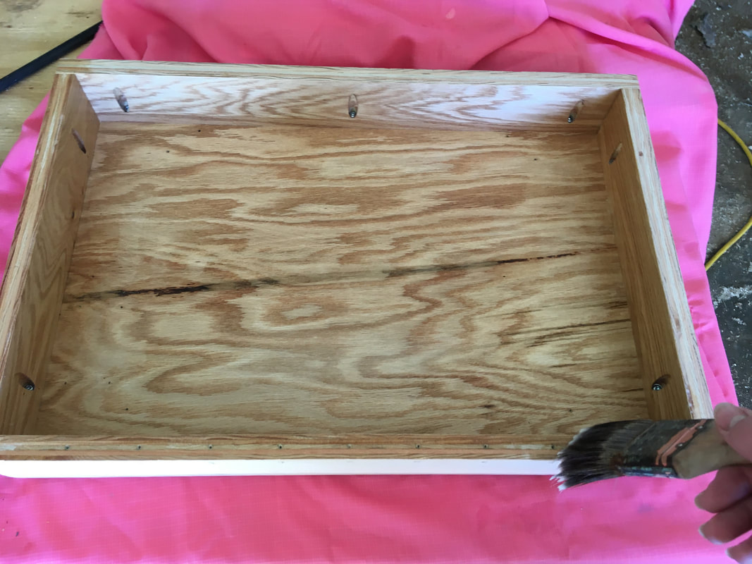
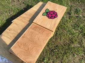
Once I gave the lid 24 hours for the paint to dry, I moved onto the sealing step. I used a water-based polyurethane sealer called Polycrylic. I started with the inside of the lid, then I put it onto a stand in the sun, and started on the inside of the bottom. I put a total of 3 coats on the inside, swapping them out as they dried. Next, I sealed the outside of the lid, and as that dried, I did the outside of the bottom, using the same tactic as the insides. For the outsides, I put a total of 5 coats of sealer, as the outside needs to stand up to a lot more than the insides. This took the majority of 3 hours of an afternoon. I was very pleased with the result, as the sealer enhanced the look of the oak plywood. This was the last component of my project before I could reassemble it for the final time.
Final Assembly
|
|
|
|
|
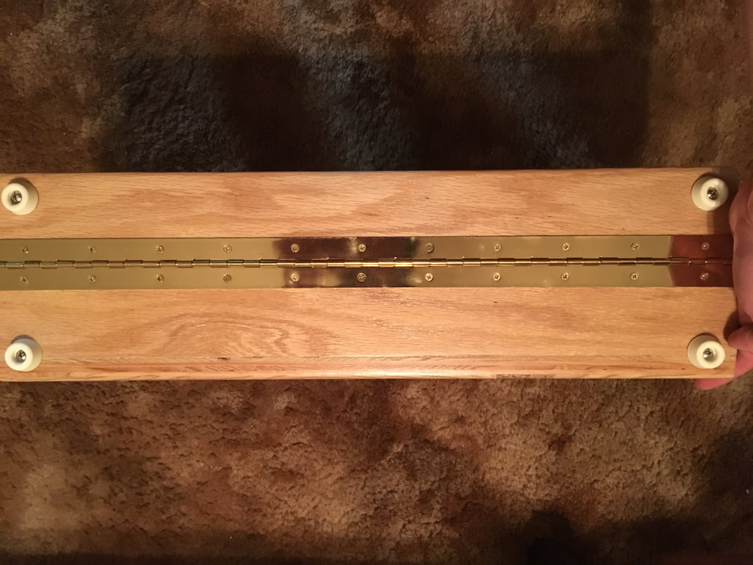
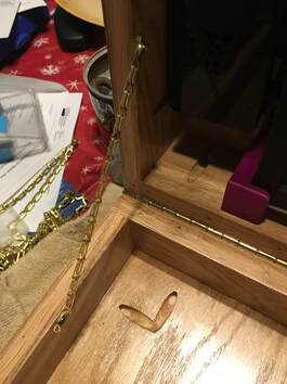
At long last, I was able to reassemble my semester project for the final time! It was much easier than the first time, as all I had to do was line up the parts with their designated screw holes, and put it back together. This process went very well, without a lot of problems. I also put on rubber feet on the bottom edges of the lid and bottom so that I could set it on the ground without scratching the hinge. In addition, I also added two brass chains on either side on the inside of the briefcase to hold it open exactly how much I wanted it.
Final Project and Final Notes
|
|
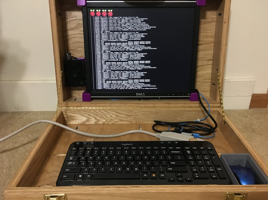
I noticed a major problem once I had my semester project completely reassembled. For no particular reason that I can figure out, when I turned on my computer, the familiar loading screen popped up, but when it ran through the code to boot up the Raspberry Pi, it stopped about 3/4 of the way through, saying that there was an error with something in the Pi. This means that my Raspberry Pi 2.0 is unable to be used until the problem is fixed. My code that was on the Pi is now inaccessible to work with, so I can't finish the code for the start up sequence. I now believe that I have my work cut out for me for the summer, so that I can use my computer with my Raspberry Pi 2.0. Other than that, my Raspberry Pi 2.0 computer works perfectly as it should.
Summary
There were a lot of things that I learned throughout the course of this project. First and foremost, I learned that it is never too early to start your semester project in Big IDEA. A lot of research and work goes into the project even before you can start the project itself. I was constantly adjusting my schedule in order to finish my computer on time. The next important thing that I learned with this project was to double-check a 3-D print to be absolutely sure that it will work with your design. I realized this only after I printed a complete set of screen mounts, only to realize that they were completely useless. I then had to go back to the drawing board and fix my design, which didn't help with the slight time crunch that I was already in. In addition, the importance of measuring twice and cut once was reiterated to me, as it helped me avoid major problems later on in the project's development.
Finally, I gained the knowledge wisdom to make absolutely sure that you have enough 3-D filament in the 3-D printer, so that you don't have to start over. This happened twice with my 3-D printed parts, with both the mouse mount and the Raspberry Pi mount. The mouse mount was just finished with a different gray instead of silver, which actually didn't take away from the project that much. With the Raspberry Pi mount, the MakerBot ran out of filament and placed the filament incorrectly due to an inconsistency with the PLA. I will now plan ahead for these problems in the future.
In summary, my semester project for Big IDEA was a very educational learning experience, and I learned a lot from it. This project gave me more freedom than any other class that I had previously, which helped me to individualize my learning experience. I hope that in the future, I will be able to apply what I learned in the Innovation Center to future technology education classes so that I can improve my learning experience throughout high school.
